Welcome to the E-Logbook 3.4.0 Tutorial.
Click to go directly to any of the following contents:
8. FLIGHT HARDWARE COMPONENT INSTALLATION LOG
8.2. FHW Component Installation Report
8.3. FHW Component Installation
8.3.1. FHW Component Installation Stages
The first thing you need to know is how to start E-Logbook:
· Click on the Start E-Logbook icon in the Desktop.
The first window you will see will prompt you to connect to the database. An example of the Connect Window is below.
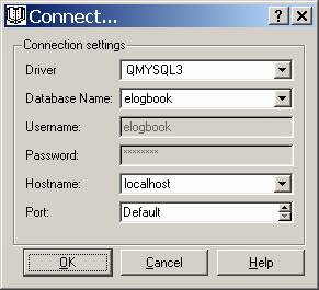
Make sure the following information appears in the window:
- Driver: MYSQL3
- Database Name: elogbook
- Username: elogbook - Disabled
- Password - Disabled
- Hostname: localhost
- Port: Default
Click OK when done.
Cancel will exit the program without saving changes.
Help will give you the same instructions as stated above.
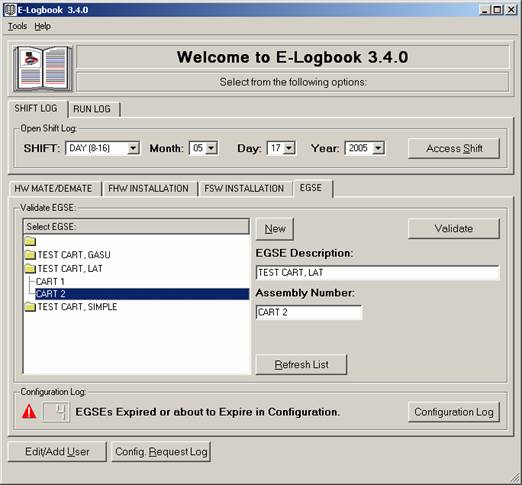
One you have entered the database parameters you will arrive to the Main Window:
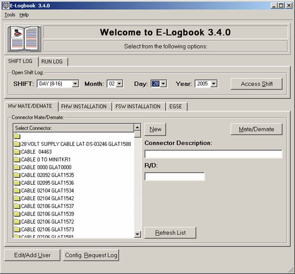
E-Logbook consists on several logs that will allow you to maintain I&T activities:
1. I&T facility User Log.
2. Shift Log.
3. Run Log.
4. EGSE Log.
5. HW Connector Mate/Demate Log.
6. FHW Component Installation Log.
7. FHW MMR Log.
8. FSW Component Installation Log.
9. FHW, FSW and EGSE Configuration Logs.
10. Configuration Request Log.
The User Log is a list of all users that have worked at some point in the I&T facility. Below are the instructions to maintain user information. To access the User Log:
- Click on Edit/Add User in the Main Window; or
- With the cursor on top of the Main window press Alt+u.
The User Log window will open:
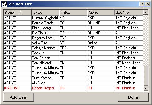
This list is sort able. The status column shows if the user is Active or Inactive in the database, i.e. if he/she is still working at the I&T facility.
In order to make any modifications or additions to the list of users you will need to have administrative privileges. In order to add a new user:
- Click on the Add User button
- Fill in the Admin username and password window:
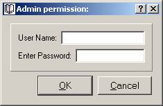
- If the Admin is accepted you will access Edit/Add User Window:
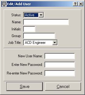
Fill in the Status (Active/Inactive), Name, Initials (only three initials), Group and Job Title.
Create a username and a password (re-enter the password to ensure it is the right one).
Click OK.
MAKE SURE YOU REMEMBER YOUR USERNAME AND PASSWORD AND ENTER THE RIGHT INFORMATION.
You will see the new user Status, Name, Group and Initials appear on the User List.
In order to make changes to an existing user double click on its entry in the user list and then follow the steps above.
If you change your mind click Cancel to exit the window.
The Shift Log is one of the core Logs that is part of E-Logbook. In it you will maintain a detailed record of all the activities performed during a shift in the I&T facility. Since the runs performed on the hardware are directly fed into this log, you will virtually find any information you need to know about a shift. In order to access the Shift Log:
- In the Main Window select the Shift and Date (month, day and year) you want to access. The current Shift and Date appear as default.
- In the Main Window click Access Shift; or
- With the cursor on top of the Main window press Alt+s.
The Shift Log window will open:
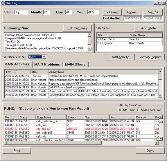
All lists in the Shift Log are sort able. There are four kinds of activities that can be performed in the Shift Log:
- Browse Shifts.
- Summary/Plan entry.
- Shifter Sign In.
- Activity entry.
- Visualize Runs
- Access Run Reports.
There are three buttons in the Shift Log window for fast browsing between contiguous shifts. In order to go to the previous or next shift, or refresh the current shift to fetch new runs:
- In the top left of the Shift Log window click Prev, Next or Refresh; or
- With the cursor on top of the Shift Log window press Alt+v, Alt+x or Alt+e.
The summary/plan is the description of the goals and activities assigned to a shift. The test conductor will typically fill in this category.
To edit the summary/plan:
- In the Shift Log window click on Edit Summary; or
- With the cursor on top of the Shift Log window press Alt+m.
The Edit Summary window will appear:
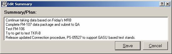
- Edit the shift summary/plan.
- Click Save.
The summary/plan will be updated in the Edit Shift window.
If you change your mind click Cancel to exit the window.
The shifter table shows the list of users that have signed in to a certain shift. To access the shifter signup window:
- Click on Add Shifter in the Shift Log window; or
- With the cursor on top of the Shift Log window press Alt+s.
The Shifter Signup window will appear:
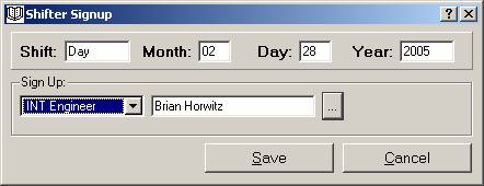
To add a shifter:
Select the job title. In a combo box like this one you can go faster to the element of the list you are interested in by typing the first letter. For example, if you are an ELX Engineer type E and the first title that starts with E will be selected, and you can drop down the list from there.
Click on the button right to the blank window. You can also press tab until this button is selected and then press enter.
Enter your username and password.
Click Save.
The Shifter list will be updated in the Shift Window.
If you change your mind click Cancel to exit the window.
There are three kinds of activity entries that a shifter can make in the Shift Log: activity, problem and other.
- An Activity is any kind of entry that indicates some work or procedure accomplished during the Shift.
- A Problem is an entry that will show a problem encountered during the activities performed in the Shift.
- Other is any other entry that does not fit into the categories described above.
In order to add an activity:
- In the Edit Shift window click Add Activity; or
- With the cursor on top of the Shift Log window press Alt+a.
The Edit Activity window will open:
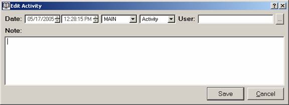
In this window you will enter following information:
Date: Timestamp of the entry, automatically entered.
Subsystem: Subsystem that the activity corresponds to, typically the subsystem the user belongs to; for example INT, CAL, etc. The subsystem is automatically pre-selected from the value in the preferences menu.
Type: Activity, Problem or Other, as defined above. Make sure you change the activity type for a problem.
User: Personal stamp on the entry. When you find this setup, click the three dotted button and enter the username and password. (You cannot add an entry until the user has been entered).
Note: Description of the activity. Please be aware that the note has a limit of 4000 characters due to Oracle database constraints. If your note is longer than that, for example a bug note, break it down and log it in sequential entries.
Click Done or press Alt+D to save the entry, or click Cancel (press Alt+C) if you change your mind and want to cancel the entry. The corresponding table will be updated in the Shift Log window.
- In the Shift Log window select the subsystem the activity corresponds to.
- Go to the Activity, Problem or Other tab that corresponds to the activity type.
- Hoover on top of the note to view it as tooltip; or
- Double click on activity to review the full entry.
In order to review all at once all the activities performed in a shift you can use the Activity Report. The Activity Report will refresh as new activities are entered or a new shift is selected by using the browse buttons of the Shift Log window. To access the Activity Report:
- In the Shift Log window click Activity Report; or
- With the cursor on top of the Shift Log window press Alt+r.
The Activity Report window will open:
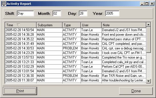
To view the whole note of an existing entry:
- Hoover on top of the note to view it as tooltip; or
- Double click on the entry.
Click Done or Ald+D to close the Activity Report window.
The last table on the Shift Log window holds the list of all the runs of electronic tests performed on the hardware during that shift. This list is automatically fed into the Shift Log via Run Control.
Things you need to know about the Runs List:
- This list is sort able as all the lists in the Shift Log.
- You can toggle between SLAC Local and GMT time by clicking the corresponding radio button in the Display Time Zone box. If you use browse shifts using the buttons on the Shift Log your time zone selection will be kept.
- Runs with Event errors of the following types appear in red: Error Event Count, Packet Error Event Count or Trigger Parity Error Event Count.
The Run Report window holds all the available information of a run recorded via Run Control. In order to access the Run Report:
· In the Shift Log Run List double click on the run of interest.
The Run Report window will open:
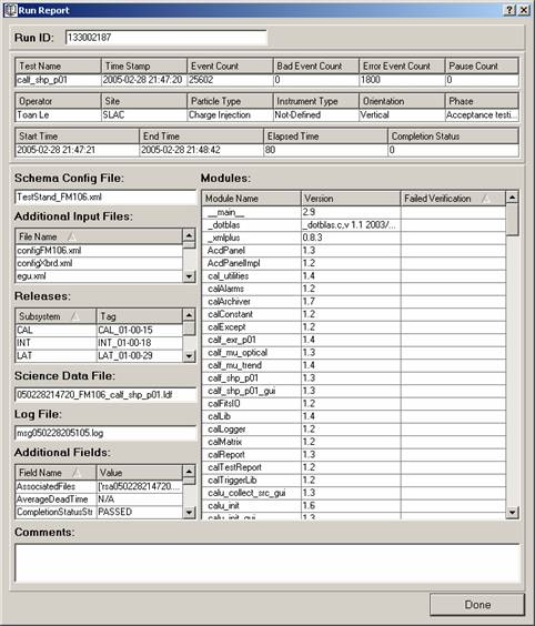
In the Run Report:
· The Run ID is displayed at the top of the window.
· Modules that failed verification are displayed in red.
· If there is Packet Error Event Count or Trigger Parity Error Event Count they will be displayed in red in the Additional Field List.
Click Done or press Alt+D when you are finished to close the Run Report window.
You can directly access the Run Report of a certain run from Main window. To do so:
· In the Main window go to the Run Log tab.
· Type the Run ID you want to display the report of.
· Click on Run Report; or
· With the cursor on top of the Main window press Alt+n.
If the Run ID is valid the Run Report window will be displayed. For more information go to 4.7.
This section of ELogbook will allow you to log and visualize information corresponding to EGSE record creation and validation activities.
6.1. Viewing an EGSE Validation Record
From the main window there are two distinctive ways of accessing EGSE record information:
![]()
![]()
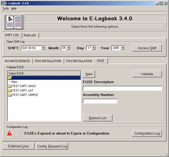
- EGSE Validation Report: A list of all records created for A CERTAIN EGSE. In order to access the EGSE Report select a EGSE from the list and click Validate.
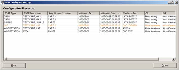
- EGSE Validation Configuration Log: A list of the latest records of ALL EGSEs. The configuration log is a snapshot of the CURRENT STATE of the EGSE system. In order to access the EGSE Configuration Log click the Configuration Log button.
 |
- If an EGSE validation record has expired or is about to expire it will be shown with the following color code:
- If a validation is expired it will show in red.
- If a validation is about to expire it will show in orange.
- Double click on any of the records in order to review it, add notes to it, or revalidate (see below how to do this).
6.2. Creating an EGSE Validation Record
There are three steps you will always need to follow in order to create an EGSE validation record in E-Logbook:
1) Select the EGSE unit you want to create a record of.
2) Access the EGSE unit Report or Configuration Log to monitor which records have been already created for this unit.
3) Create the record by clicking add from the report window.
6.2.1. New EGSE
If the EGSE you are about to validate is not in E-Logbook you will have to create it:
- In the Main Window EGSE tab make sure that the empty folder is selected in the connector list and click New.
![]()

The EGSE record window will appear:
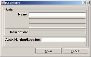
· Enter the Name of the EGSE you want to create a record of.
· Enter the EGSE Assy. Number; or in case of a Workstation type EGSE, its location.
· Click Save.
· The new EGSE will appear in the EGSE List in the main window and will also be selected.
You can also create a new Assy. Number/Location for an existing EGSE in a quick way:
· Select the EGSE from the EGSE List in the Main window.
· Click New. The EGSE record window will appear, this time with the Name already entered, and read only:
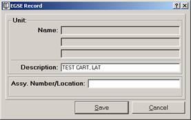
· Enter the new Assy. Number/Location.
· Click Save.
· The new EGSE will appear in the EGSE List in the Main window and will also be selected.
If you change your mind click Cancel.
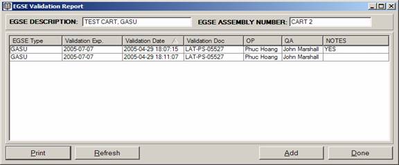
6.2.2. EGSE Validation Report
Once the EGSE you want to create a validation record of is listed the Main window, you can proceed to access its report. The EGSE Report will list all validation records created on a certain EGSE thought the lifetime of I&T.
- In the Main Window EGSE tab select the EGSE from the EGSE List. Make sure that the EGSE Description and Assembly Number/Location fields are filled with the information of the EGSE you have selected.
- Click Validate. You can alternatively double click the EGSE in the list.
The EGSE Validation Report window will appear:
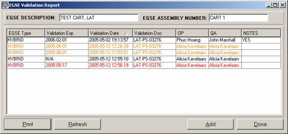
- This window reports the history of all the EGSE validations performed on a certain EGSE unit.
- In order to check if an EGSE needs revalidation make sure you browse for the latest record as indicated by the Validation Date. A better tool to monitor record revalidation is the Configuration Log described below.
- It also shows if an EGSE validation record has comments.
- It is printable (click Print on the bottom left of the window).
- It can be refreshed on demand (click Refresh on the bottom left of the window or press F5).
There are two activities you can perform in this window:
· Access a certain EGSE Validation Record: you can do this by double clicking on the record you are interested on.
· Create a new EGSE Validation Record: click Add in the bottom right of the window.
Click Done or the X in the top right corner of the window when you are finished with the report.
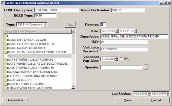
6.2.3. EGSE Validation Record
The EGSE Validation Record is the heart of the EGSE part of E-Logbook:
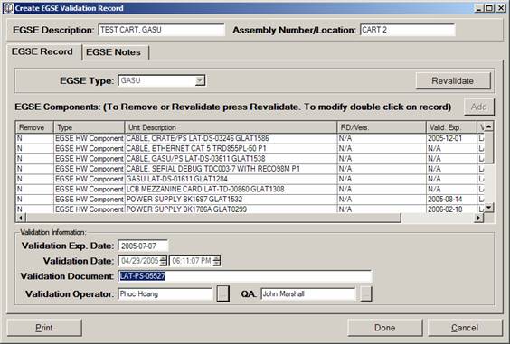
In order to create an EGSE Validation Record you need to enter the following information:
· EGSE Type
· EGSE Components
· Validation Document
· Validation Operator and QA
The Validation Expiration Date is automatically determined from the earliest expiration date in the list of EGSE Components.
6.2.3.1. Add EGSE Components
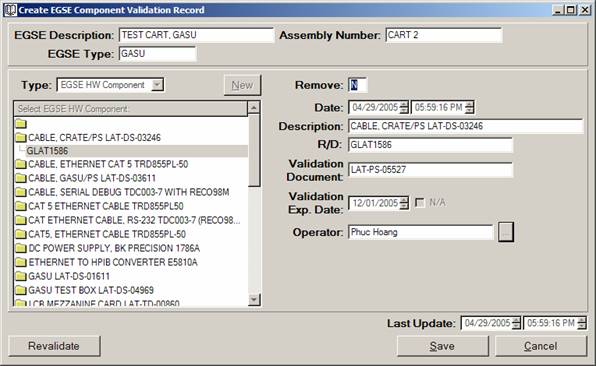
In order to add an EGSE Component you need to enter the following information:
· Select EGSE Component Type:
o HW Connector
o FHW Component
o EGSE HW Component
o EGSE SW Component
o EGSE (for Hybrid EGSE that are created from other EGSE assemblies)
· Select EGSE Component from the list, such that you display:
o If the EGSE Component is not in the corresponding EGSE Type list click New in order to add it to the list of current and future selection (in order to do so follow the same steps as in 6.2.1).
· Remove and Date are automatically entered for you.
· Description and R/D display your current EGSE Component selection from the list.
· Enter the Validation Document.
· Enter the Validation Expiration, or N/A if Not Applicable.
· Enter the Validation Operator.
Repeat this operation as many times needed in order to enter all the components in the EGSE Record you are about to validate. Once the list is complete finish up by adding the validation document and OP and QA stamp, and press Save.
You can always access the record in order to add comments. Press Cancel at any time to abort the creation of the record. Please note that all information added, including EGSE Component information, will be lost.
Once you press Save the newly created EGSE Validation record will appear both in the EGSE Report and Configuration Log windows, with the appropriate color code.
6.3. Revalidate EGSE
For EGSE that has expired or is about to expire validation you will need to revalidate by updating the information on E-Logbook. In order to revalidate EGSE you can create a new Validation Record from scratch or if possible you will be better off by revalidating the an existing record.
In order to do this:
· Access the EGSE Validation Report and select the latest EGSE Validation record; or
· Access the EGSE Configuration Log and select the EGSE Record you wish to revalidate.
Once you access the EGSE Validation Record click on Revalidate. This will enable all the fields for update.
In order to update/revalidate the list of EGSE Components there are several things you can do:
· You can Add/Remove a Component by selecting Yes or No from the drop down list in the Remove column.
· You can click the Add button in order to add more EGSE Components to the list.
· You can double click on an existing component in order to update its information. In order to do so you will need to click revalidate once you access the component window:
![]()
The Component T
· The EGSE Component Type, Description and R/D will be pre-selected in order to maintain the current component information.
· The Validation Document, Expiration Date and OP will be enabled to be updated.
You can always press Cancel at any time in order to abort the Revalidation. Please note that all changes, removes and adds made to the EGSE will be lost.
Note: You can also revalidate from an EGSE Record other than the latest one in the EGSE Report if it contains a list of components that is closer to the list you need to create for the new EGSE Validation Record.
This section of ELogbook will allow you to log and visualize information corresponding to HW Connector Mate/Demate activities.
7.1. Viewing a M/D Record
In order to access a M/D record:
- In the Main Window HW Mate/Demate tab select a connector from the connector list. In a list view like this one you can go faster to the element of the list you are interested on by typing the first letter. For example, if you want to mate/demate a TEM-PSU Assy., type T and the first TEM-PSU Assy. in the list will be selected. You can then scroll down to the TEM-PSU Assy. you are interested on.

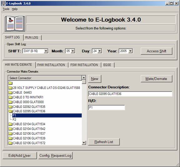
- Click on Mate/Demate to access the M/D Report.
- Double click on the M/D Record you are interested on.
7.2. Creating a M/D Record
There are three steps you will always need to follow in order to create a M/D Report in E-Logbook:
1) Select the HW Connector you want to create a record of.
2) Access the HW Connector Report to monitor which records have been already created for this unit.
3) Create the record by clicking add from the report window.
7.2.1. New HW Connector
If the connector you are about to mate/demate is not in E-Logbook you will have to create it:
- In order to create a new connector, in the Main Window HW Mate/Demate tab make sure that the empty folder is selected in the connector list and click New:
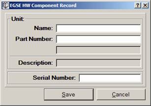
The HW Connector Record window will appear:
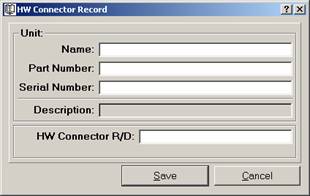
· Enter the Name, Part Number, and Serial Number of the Unit the connector belongs to.
· Enter the Connector R/D.
· Click Save.
· The Unit information will be combined into a Unit Description.
· The New Connector will appear in the Connector List and will also be selected (the Description and R/D fields will show the new connector information).
You can also create a new R/D for an existing Unit in a quick way:
· Select a Unit Description from the Connector List.
· Click New. The Connector Information window will appear, this time with the Unit Description already entered:
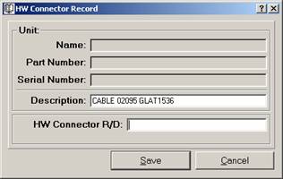
· Enter the new R/D.
· Click Save.
· The New Connector will appear in the Connector List and will also be selected.
If you change your mind click Cancel.
- In the Main Window HW Mate/Demate tab select a connector from the connector list. Make sure that the Unit Description and Connector R/D fields are filled with the information of the connector you have selected.
- Click Mate/Demate.
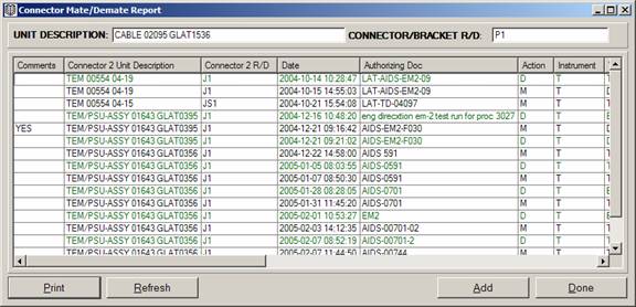
The Connector Mate/Demate Report window will appear:
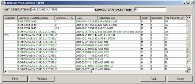
- This window reports the history of all the Mate/Demates performed on the selected connector.
- It shows if a Mate/Demate record has comments.
- It is printable (click Print on the bottom left of the window).
There are two activities you can perform from this window:
· Review a Mate/Demate Record: Double Click on an entry and you will access the full record of that Mate/Demate.
· Add a Mate/Demate Record: Click Add. The current status of the Connector will be shown:
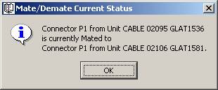
Once you have performed one of the two options above you will access the Create Mate/Demate window:
7.2.3. Mate/Demate Record
The Create (or View if an existing record is selected) Mate/Demate window will appear:
![]()
![]()

In this window you can log all of the following HW Connector Mate/Demate information:
· Mate or Demate:
o You can’t Mate/Demate a connector to itself.
o You can’t Demate a currently Mated connector.
· Flight or Test hardware.
· Date: The date the current record is created.
· Authorized by document: The procedure document you are following for the Mate/Demate.
· 2nd connector you are going to Mate/Demate to. If the connector is currently mated this information is given to you, and the only operation you are allowed to perform is a Demate. If the 2nd connector is not in the list you will need to add it by clicking new and following the instructions in 7.2.1.
· Operator and QA stamps for all the Mate/Demate activities.
· In case of Mate:
o You will need to enter the Torque information (see below).
· Comments: Can be added to an existing record only.
· Last Modified: The time when the log entry was last modified by adding a new comment. If there are no comments it will be the same as Date.
7.2.4. Add Torque Information
In case of a Mate you will need to enter the Torque information as well as OP and QA. In order to do so click on the Add button. You will access the Torque window, where you will have to enter the following information:
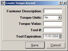
· Fastener Description.
· Torque Value in the selected units.
· Tool #.
· Tool Expiration.
In order to create a record you must have all fields filled in other than the comments. Click Save in order to create the record. Click Cancel in order to abort the entry, all changes will be lost.
8. FLIGHT HARDWARE COMPONENT INSTALLATION LOG
This section of E-Logbook will allow you to log and visualize information corresponding to Hardware Component Installation activities.
4) In the Main Window FHW Installation tab select a component from the component list. In a list view like this one you can go faster to the element of the list you are interested on by typing the first letter. For example, if you want to install a TEM-PSU Assy., type T and the first TEM-PSU Assy. in the list will be selected. You can then scroll down to the TEM-PSU Assy. you are interested on.
5) If the component you are about to install is not in E-Logbook you will have to create it:
First select which component you want to work on in the main window. If the component is not in the database you will have to create a new component as follows.
- In order to create a new component, in the Main Window FHW Installation tab make sure that the empty folder is selected in the component list and click New:
The Component Information window will appear:
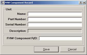
· Enter the Name, Part Number, and Serial Number of the Unit the component belongs to.
· Enter the Component R/D.
· Click Save.
· The Unit information will be combined into a Unit Description.
· The New Component will appear in the Component List and will also be selected (the Description and R/D fields will show the new component information).
You can also create a new R/D for an existing Unit in a quick way:
· Select a Unit Description from the Component List.
· Click New. The Component Information window will appear, this time with the Unit Description already entered:
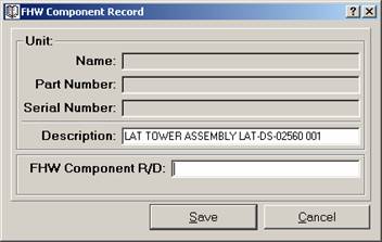
· Enter the new R/D.
· Click Save.
· The New Component will appear in the Component List and will also be selected.
If you change your mind click Cancel.
8.2. FHW Component Installation Report
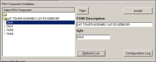
- In the Main Window HW Installation tab select a component from the component list. Make sure that the Unit Description and Component R/D fields are filled with the information of the component you have selected.
- Click Install.
The FHW Component Installation Report window will appear:
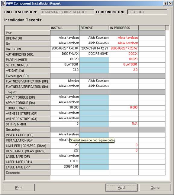
- This window reports the history of all the Installation activities performed on the selected component. There are three categories: Install, Remove and In Progress.
- It is printable (click Print on the bottom left of the window).
There are two activities you can perform from this window:
- Review a FHW Component Installation Record: Double Click on a column entry and you will access the full record of that FHW Component Installation activity.
- Add a FHW Component Installation Record: Click Add.
You will access the Create HW Component Installation window:
8.3. FHW Component Installation
The Create FHW Component Installation window will appear:
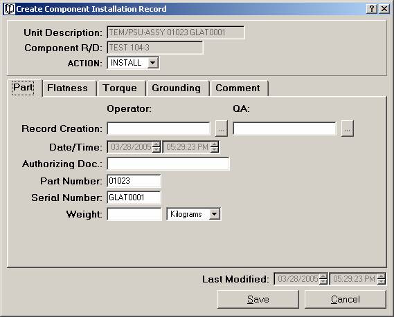
In this window you can log all of the following HW Component Installation information:
· Selected component R/D and description (given).
· Selected component Part Number and Serial Number (given from description, can be modified).
· Date: The date the current record is created (current date, given).
· Installation Stages’ general guidelines:
· You must fill in sequentially ALL fields related to a certain installation stage (flatness, torque installation, MMR, grounding, label tape) in order to save the changes.
· Enter units in International System, you can toggle afterwards between IS and English System.
· Enter a resistance ABOVE the Limit Per value.
· Enter a future date for the Label Tape Expiration.
· Operator and QA stamps: must verify EVERY installation stage.
· Comments: can be added to an existing record only.
· Last Modified: The time when the log entry was last modified by adding a new stage or comment.
The different installation stages are QA verified. As long as all the fields corresponding to a certain stage and the QA verification have not been entered, E-Logbook won’t let you save the record.
8.3.1.FHW Component Installation Stages
Once the record is saved up to a certain stage, all the information entered won’t be modifiable.
The fields corresponding to the component installation information are:
- Activity: Install or Remove.
- Authorization document: The procedure document you are following for the installation.
- Component Weight: To be filled in kilograms up to the third decimal point.
Flatness
The fields corresponding to flatness are:
- Flatness verification operator and QA stamp.
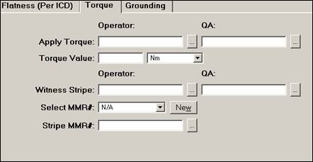
The fields corresponding to torque value are:
- Torque Value.
- Torque value operator and QA stamp.
MMR:
The fields corresponding to torque MMR are:
- The witness stripe MMR#: selected from a list of the currently existing MMR. It points to the corresponding MMR Log, which you can open if you need to.
- Operator that applied the witness stripe and QA stamp.
Select the Grounding tab window:
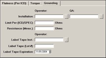
Resistance:
The fields corresponding to grounding resistance are:
- Operator and QA stamp.
- Limit Per value: in ICD/SPEC.
- Resistance: must be higher than the Limit Per value.
Label Tape:
The fields corresponding to label tape installation are:
- Operator and QA stamp.
- Label Tape Lot #.
- Label Tape Expiration: must be a future date.
This section of E-Logbook will allow you to log and visualize information corresponding to Material Mix Record activities.
6) In the Main Window FHW Installation tab select a MMR# from the MMR list. In a list box like this one you can go faster to the element of the list you are interested on by typing the first digit. For example, if you want to go to MMR # 19, type 19 and you will go to MMR # 19 directly. Click View.
7) If you want to create a new MMR click New.
The Create MMR window will appear:
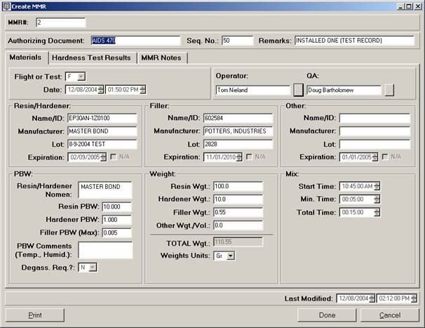
- This window reports all the information related to a certain MMR.
- It is printable (click Print on the bottom left of the window).
- In order to create a MMR the following fields must be entered:
Authorizing Document
Seq. No.
Remarks: If the Material is only Resin, or Other than Resin/Hardener and Filler. For example if it has been purchased in pistol format and therefore already mixed.
Operator and QA stamp.
At least one of the three kinds of materials (Resin/Hardener, and/or Filler, and/or Other) information:
Name/ID: of the material.
Manufacturer
Lot
Expiration: click N/A if it is Not Applicable
PBW (if applicable).
Weight (if applicable).
Resin/Hardener PBW Nomenclature (if applicable).
Degas Required (if applicable): Yes or No.
Mix Times (if applicable): Total Time must be greater than Minimum time.
Once the MMR is created E-Logbook will generate a MMR#.
You can add MMR notes to an existing MMR only.
Last Modified: This field will show the time when the log entry was last modified by adding new information or MMR notes.
A Hardness Test must be performed on the mix after the indicated time in the MMR procedure document. To enter the information related to the Hardness Test Result in the MMR Log:
· In the Main Window or the Create HW Component Installation window (Torque tab) select the MMR# and click to open it.
· Go to the Hardness Test Results Tab.
The Hardness Test Results tab looks like the following window:
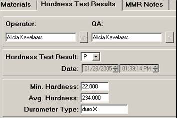
The Hardness Test Results information you need to enter is the following:
· Operator and QA stamp.
· Minimum Hardness required by the procedure document.
· Average Hardness achieved.
· Test Result:
o If the Average Hardness is ABOVE the Minimum Hardness the test has Passed (P).
o If the Average Hardness is BELOW the Minimum Hardness the test has Failed (F).
· Durometer Type.
If you have any questions, please contact:
Alicia T. Kavelaars aliciak@SLAC.Stanford.edu
Selim Tuvi stuvi@SLAC.Stanford.edu
Ric Claus claus@SLAC.Stanford.edu
Or visit the E-logbook website @
http://www-glast.slac.stanford.edu/IntegrationTest/ONLINE/ELogbook/index.htm
We would love to hear your input and new ideas on how to improve Elogbook.