E-Logbook Tutorial
Welcome to E-Logbook Tutorial.
Click to go directly to any of the following contents:
2.1. E-Logbook’s Preferences Menu
4.4.2. Review an activity entry
6.1.1.1. Create a New HW Connector Record
6.1.2. Access the Mate/Demate Report
6.1.3. Create the Mate/Demate Record
6.1.3.1. Add the Torque Information
7. FHW
COMPONENT INSTALLATION LOG
7.1. Create a FHW Component Installation
Record
7.1.1.1. Create a New FHW Component Record
7.1.2. Access the FHW Component
Installation Report
7.1.3. Create the FHW Component
Installation Record
7.1.3.1. FHW Component Installation Part
Stage
7.1.3.2. FHW Component Installation
Flatness Stage
7.1.3.3. FHW Component Installation Torque
Stage
7.1.3.4. FHW Component Installation MMR
Stage
7.1.3.5. FHW Component Installation
Grounding Stage
7.1.3.6. FHW Component Installation Label
Tape Stage
7.2. Create a FHW Component Removal Record
7.3. Review FHW Component Installation
Records
9. FSW
COMPONENT INSTALLATION LOG
9.1. Create a FSW Component Installation
Record
9.1.1.1. Create a New FSW Component Record
9.1.2. Access the FSW Component
Installation Report
9.1.3. Create the FSW Component
Installation Record
9.2. Review FSW Component Installation
Records
10.1. Creating
an EGSE Validation Record
10.1.1.1. Create a New FHW Component Record
10.1.2. Access the ESGE Validation Report
10.1.3. Create the EGSE Validation Record
10.2. Review
EGSE Validation Records
10.3.1. Revalidate EGSE Components
11.1. Reports
versus Configuration Logs
11.2. Access
the Configuration Logs
11.3. The
EGSE Configuration Log
11.4. CONFIGURATION
REQUEST LOG
E-Logbook is a
program that will help you log and monitor all the Integration and Testing
activities performed for the GLAST LAT project.
In order to access E-Logbook:
- Click on the Start E-Logbook icon in the Desktop.
- The Connect window will appear: this window will prompt you to connect to the database. An example of the Connect Window is below.
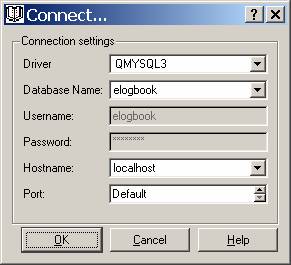
- This window will prompt you to connect to the database Make sure the following information is entered:
· Driver: MYSQL3
· Database Name: elogbook
· Username: elogbook - Disabled
· Password - Disabled
· Hostname: localhost or glast03
· Port: Default
- Click OK (press Alt+o) to access E-Logbook.
· Click Cancel (press Alt+c) or press X in the upper right corner of the window to exit E-Logbook.
· Click Help (press Alt+h) to access the same instructions as described here.
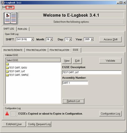
One you have entered the database parameters you will arrive to E-Logbook’s Main window:
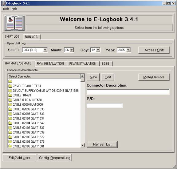
E-Logbook consists on several components:
- I&T facility User Log.
- Shift Log.
- Run Log.
- EGSE Log.
- HW Connector Mate/Demate Log.
- FHW Component Installation Log.
- FHW MMR Log.
- FSW Component Installation Log.
- FHW, FSW and EGSE Configuration Logs.
- Configuration Request Log.
Each of these components can be accessed from one of the tabs in the Main window, by clicking in the corresponding buttons. Detailed instructions on how to use the components’ features follow.
2.1. E-Logbook’s
Preferences Menu
The Preferences Menu creates a set of defaults that is maintained throughout the window system. These preferences are saved once E-Logbook is closed for future use. There are currently two parameters that can be defaulted in E-Logbook:
· Shift Log Subsystem.
· EGSE Validation Expiration Limit.
To access and edit E-Logbook’s Preferences Menu:
1. In the Main window Menu Bar, click on Tools (press Alt+t).
2. The Preferences window will appear:
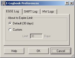
3. Update EGSE Log Preferences: Select the number of days in advance you wish to be noticed that EGSE Validation Records are about to expire. By default this value is 30 days.
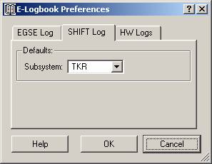
4. Update Shift Log Preferences: Select the Subsystem you wish to have by default in the Shift Log. This will help the entry of Activity, Problem or Other notes.
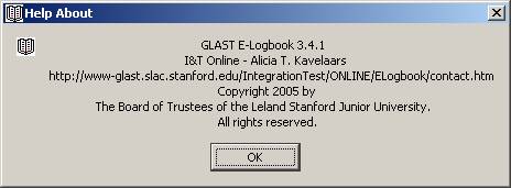
The Help Menu links to a set of aids that will help you learn more about E-Logbook.
To access and edit E-Logbook’s Preferences Menu:
In the Main window Menu Bar, click on Help (press Alt+h).
There are currently three links in the Help Menu:
· Manual: Will direct you to an online version of this tutorial.
· Website: Will direct you to E-Logbook’s official website, located at:
http://www-glast.slac.stanford.edu/IntegrationTest/ONLINE/ELogbook/index.htm
· About: Will show you E-Logbook’s current version information.
The User Log contains a list of all the users that have worked at some point in the I&T facility.
To access the User Log:
- Click on Edit/Add User in the Main Window; or
- With the cursor on top of the Main window
press Alt+u.
The User Log window will appear:
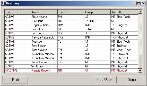
The status column shows if the user is Active or Inactive in the database, i.e. if he/she is still working at the I&T facility.
The list is sort able. Just click on the header of the column you wish to sort by. All the records in the list will be sorted accordingly in ascending order. If you click the header again the list will be sorted in descending order.
In order to make any modifications or additions to the User Log a person with administrative privileges needs to log in:
1. Click on the Add User button, or with the cursor on top of the User Log window press Alt+a.
2. Fill in the Admin username and password window:
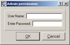
3. If the login is correct you will access the Edit User window:
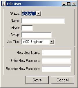
4. Fill in the Status (Active/Inactive), Name, Initials (only three initials), Group and Job Title.
5. Create a username and a password (re-enter the password to ensure a correct entry).
6. Click Save, or press Alt+s.
MAKE SURE YOU REMEMBER YOUR USERNAME AND
PASSWORD AND ENTER THE RIGHT INFORMATION.
Once you Save the record it will appear in the User Log, sorted by the currently selected column.
In order to make changes to an existing user double click on its entry in the User Log and then follow the same steps described above.
· If you change your mind click Cancel (press Alt+c) or press X in the upper right corner of the window to exit.
The Shift Log is one E-Logbook’s core components. It is used to maintain a detailed record of all the activities performed during a shift in the I&T facility. Since the runs performed on the hardware are directly fed into this log, you will virtually find any information about a shift.
In order to access the Shift Log, in the Main window:
- Select the Shift and Date (month, day and year) you want to access. The current Shift and Date appear as default.
- Click Access Shift; or with the cursor on top of the Main window press Alt+s.
The Shift Log window will appear:
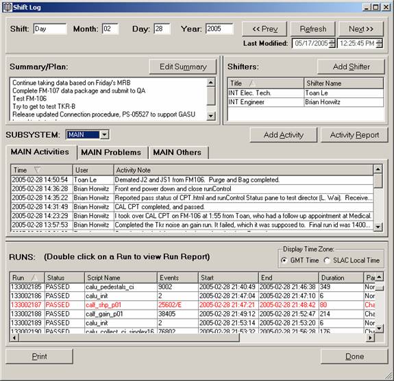
There are several activities that can be performed in the Shift Log:
- Browse Shifts.
- Summary/Plan entry.
- Shifter Sign In.
- Activity entry.
- Visualize Runs
- Access Run Reports.
- The Shift Log can be printed by clicking in the Print button or with the cursor on top of the Shift Log window by pressing Alt+p.
- All lists in the Shift Log are sort able[1].
There are three buttons in the Shift Log window for fast browsing between contiguous shifts. These buttons allow you to go to the previous or next shift, or refresh the current shift for example to fetch new runs or visualize entries currently performed in other workstations.
In order to browse shifts:
- In the top left of the Shift Log window click Prev, Next or Refresh; or with the cursor on top of the Shift Log window press Alt+v, Alt+x or Alt+e.
The summary/plan is the description of the goals and activities that the test director aims to have done during a shift. It will be then typically him/her who will fill in this entry.
To edit the summary/plan:
- In the Shift Log window click on Edit Summary; or with the cursor on top of the Shift Log window press Alt+m.
- The Edit Summary window will appear:
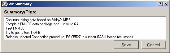
- Enter the shift summary/plan.
- Click Save; or with the cursor on top of the Edit Summary window press Alt+s.
· If you change your mind click Cancel or press X in the upper right corner of the window to exit.
The summary/plan will be updated in the Shift Log window.
The shifter table shows the list of users that have signed in to a certain shift.
To access the shifter signup window:
- Click on Add Shifter in the Shift Log window; or with the cursor on top of the Shift Log window press Alt+s.
- The Shifter Signup window will appear:
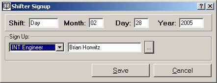
- Add the shifter information:
· Select the job title[2].
· Click on the […] password button[3] and login by entering your username and password.
- Click Save; or with the cursor on top of the Edit Summary window press Alt+s.
· If you change your mind click Cancel or press X in the upper right corner of the window to exit.
The Shifter list will be updated in the Shift Window.
There are three kinds of activity entries that a shifter can make in the Shift Log: activity, problem and other.
· An Activity is any kind of entry that indicates some work or procedure accomplished during the Shift.
· A Problem is an entry that will show a problem encountered while performing the activities during the Shift.
· Other is any other entry that does not fall into the categories described above.
In order to add an activity, problem or other entry:
1. In the Edit Shift window click Add Activity; or with the cursor on top of the Shift Log window press Alt+a.
2. The Edit Activity window will appear:
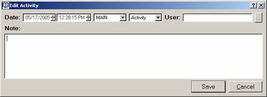
3. Enter the activity, problem or other information:
· Date is the timestamp of the entry, automatically determined by E-Logbook.
·
Subsystem is the subsystem the user belongs to;
for example
· Type: Activity, Problem or Other, as defined above. Make sure you change the activity type for a problem or other.
· User: Click on the … password button[5] and login by entering your username and password. (You cannot save the entry until the user has been entered).
· Note: Description of the activity, problem or other. Please be aware that the note has a limit of 4000 characters. If your note is longer than that, for example a bug note, break it down and log it in sequential entries.
4. Click Save or press Alt+s to save the entry.
· Click Cancel at any time (press Alt+c) or press X in the upper right corner of the window to exit without saving the entry.
The corresponding list will be updated in the Shift Log window.
4.4.2. Review an activity entry
1. In the Shift Log window select the subsystem the activity corresponds to.
2. Go to the Activity, Problem or Other tab that corresponds to the activity type.
3. Hoover on top of the note to view it as tooltip; or double click on activity to review the full entry.
4. The Note window will appear showing the subsystem and type:
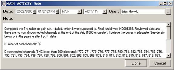
· When reviewing activity notes, the note is read only but can be selected to be copied and pasted.
5. Click Done (press Alt+d). You can also click Cancel or press the X in the upper right corner of the window to exit it.
The Activity Reports shows a list of all the activities, problems or other entries performed in a shift. The Activity Report will refresh as new activities are entered, or a new shift is selected by using the browse buttons of the Shift Log window.
To access the Activity Report:
- In the Shift Log window click on Activity Report; or with the cursor on top of the Shift Log window press Alt+r.
- The Activity Report window will open:
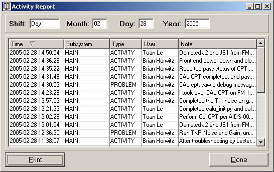
There are a couple of things that you can do in the Activity Report:
· In order to see the full note of an entry hover on top of the note to view it as tooltip; or double click on the entry. Go to section 4.4.1. for more instructions on how to review an entry.
· The Activity Report can be printed by clicking in the Print button; or with the cursor on top of the Activity Report window by pressing Alt+p.
- Click Done or press Ald+D to close the Activity Report window. You can also press X in the upper right corner of the window to close it.
The last table on the Shift Log window is the list of all the runs of electronic tests performed on the hardware during that shift. This list is automatically fed into the Shift Log via Run Control.
Things you need to know about the Runs List:
· The list is sort able as all the lists in the Shift Log[6].
· You can toggle between SLAC Local and GMT time by clicking the corresponding radio button in the Display Time Zone box. If you use browse shifts using the buttons on the Shift Log your time zone selection will be kept.
· Runs with event errors of the following types appear in red: Error Event Count, Packet Error Event Count or Trigger Parity Error Event Count.
The Run Report window shows all of the run information recorded via Run Control.
In order to access the Run Report:
- In the Shift Log Run List double click on the run of interest.
- The Run Report window will appear:
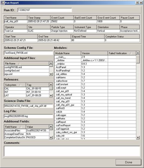
In the Run Report window:
· The Run ID is displayed at the top of the window.
· Modules that failed verification are displayed in red.
· If there is Packet Error Event Count or Trigger Parity Error Event Count they will be displayed in red in the Additional Field List.
- Click Done (press Alt+d) when you are finished to close the Run Report window. You can also press X in the upper right corner of the window to close it.
You can directly access the Run Report of a certain run from the Main window.
To access a Run Report from the Main window:
1. Go to the Run Log tab.
2. Type the Run ID you want to display the report of.
3. Click on Run Report; or with the cursor on top of the Main window press Alt+n.
· If the Run ID is valid the Run Report window will be displayed. For more information go to section 4.6.1.
4. The Run Report of the selected Run ID will appear:
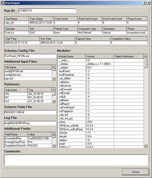
5. Click Done (press Alt+d) when you are finished to close the Run Report window. You can also press X in the upper right corner of the window to close it.
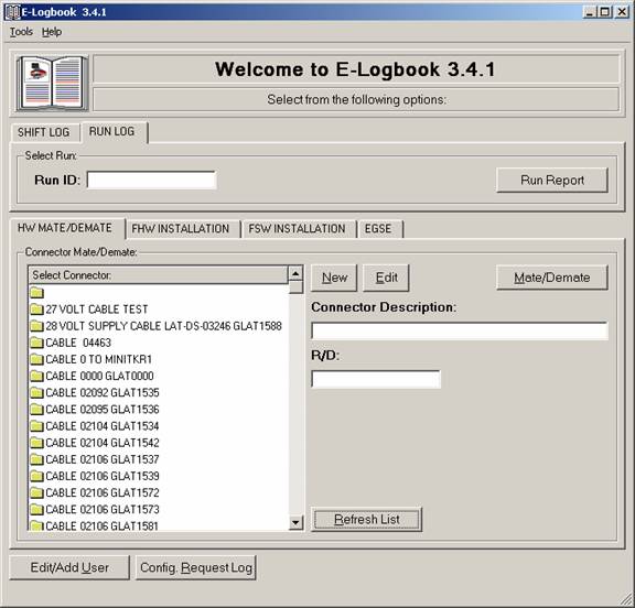
This section of ELogbook will teach you to log and visualize information corresponding to the HW Connector Mate/Demate Log.
There are three steps you will always need to follow in order to create records in E-Logbook. In particular for the M/D Log:
1. Select the HW Connector you want to create a record of.
2. Access the HW Connector Report to monitor which records have been already created for this unit.
3. Create the M/D Record by clicking add from the report window.
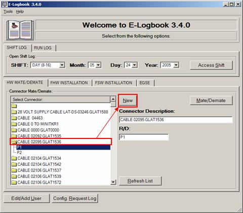
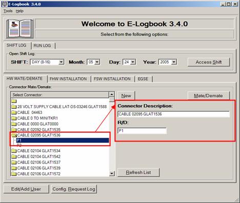
- In the Main Window HW Mate/Demate tab, select a connector from the connector list[7]. The selected connector description and R/D will be shown in the corresponding boxes to the right of the HW connector list.

6.1.1.1.Create a New HW Connector Record
If the HW Connector you are about to Mate/Demate is not in E-Logbook you will have to create it:
- In the Main Window HW Mate/Demate tab, make sure that the empty folder is selected in the connector list and click New.
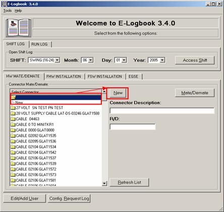
- The HW Connector Record window will appear:
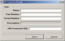
- Enter the new HW Connector information:
· Name.
· Part Number.
· Serial Number.
These fields will be combined to create the HW Connector Description.
· HW Connector R/D.
- Click Save (press Alt+s).
· Click Cancel (press Alt+c) or press X in the upper right corner of the window to exit at all times without saving the entry.
Once you click Save, the new HW Connector will appear in the HW Connector list and in the Description and R/D boxes of the M/D tab.
v To update the HW Connector list in the Main window M/D tab (at all times) click on Refresh List.
You can also create a new R/D for an existing Unit in a quick way:
- In the Main window M/D tab select the Unit Description from the HW Connector List and click new.
- The HW Connector Record window will appear, this time with the Unit Description already selected:
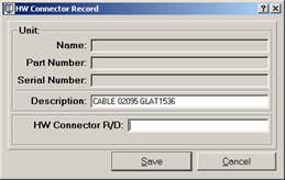
- Enter the New HW connector R/D.
- Click Save (press Alt+s).
· Click Cancel (press Alt+c) or press X in the upper right corner of the window to exit at all times without saving the entry.
Once you click Save, the new HW Connector will appear in the HW Connector list and in the Description and R/D boxes of the M/D tab.
v To update the HW Connector list in the Main window M/D tab (at all times) click on Refresh List.
6.1.2. Access the Mate/Demate Report
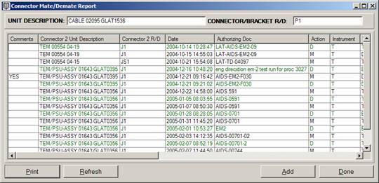
- Once the HW Connector has been selected, in the Main window M/D tab click on the Mate/Demate button[8]. The Connector Mate/Demate Report window will appear:
· This window reports the history of all the Mates/Demates performed on the selected connector. Every row is a record and every column is a field. There are as many rows as fields entered during the creation of the record.
· It shows if a Mate/Demate record has comments.
· It is printable (click Print (press Alt+p) on the bottom left of the window).
· It can be refreshed (click Refresh (press Alt+r) on the bottom left of the window), to update the list of Mates/Demates performed in the connector in the cleanroom at all times.
· You will need to click Add to create a new M/D Record, or double click on a Record (a row in the M/D Report) to review it (see the following sections).
6.1.3. Create the Mate/Demate Record
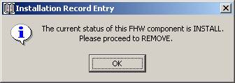
- In the Mate/Demate Report window click Add. The current status of the HW Connector will be shown:
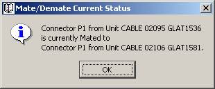
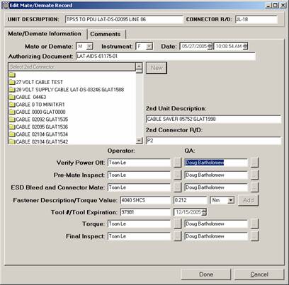
- Click OK and the Create Mate/Demate Record window will appear:
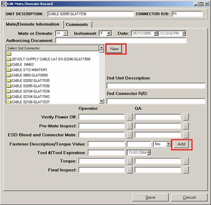
· Mate or Demate:
o You can’t Mate/Demate a connector to itself.
o You can’t Demate a currently Mated connector.
· Flight or Test hardware.
· Date: The date the record is created, automatically assigned by E-Logbook.
· Authorized by document: The procedure document you are following for the Mate/Demate.
· 2nd connector you are going to Mate/Demate to. If the connector is currently mated this information is given to you, and the only operation you are allowed to perform is a Demate. If the 2nd connector is not in the list you will need to add it by clicking new and following the instructions in section 6.1.1.1.
· In case of Mate:
o Torque information (see below).
· Comments: To be added to an existing record only (see next section).
· Last Modified: Time when the log entry was last modified by adding a new comment. If there are no comments it will be the same as Date.
- Operator and QA stamps: must verify EVERY Mate/Demate activity.
- Click Save (press Alt+s). If any information is missing you will be prompted to enter it.
· Click Cancel (press Alt+c) or press X in the upper right corner of the window to exit at all times without saving the entry.
Once all the information has been correctly entered the newly created M/D Record will appear in the M/D Report.
6.1.3.1. Add the Torque Information
In case of a Mate you will need to enter the Torque information:
- In the Edit Mate/Demate Record window click on the Add button. The Add Torque window will appear:
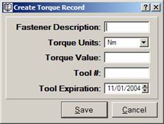
- Enter the torque information:
· Fastener Description.
· Torque Value with the correct units.
· Tool #.
· Tool Expiration.
- Click Save. If any information is missing you will be prompted to enter it. Once all the information has been correctly entered the newly created Torque Record will appear in the M/D Record window.
· Once the record is saved up to a certain stage, all the information entered won’t be modifiable.
· Click Cancel (press Alt+c) or press X in the upper right corner of the window to exit at all times without saving the entry.
Sometimes comments are needed in order to log a problem or special procedure followed during the consecution of an activity in the cleanroom.
In order to add or review a comment in any of E-Logbook’s Logs:
Click Add on the right corner on top of the comments list.
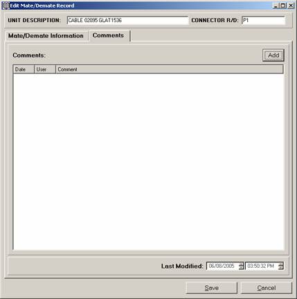
The Edit Comment window will appear:
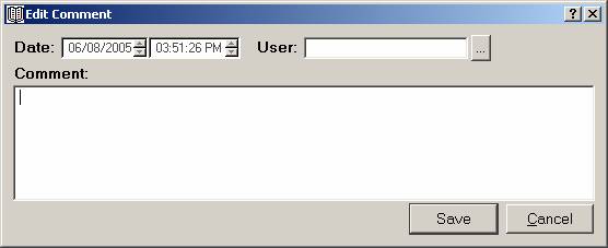
Add the Comment information:
· Date: Timestamp of the entry, automatically assigned by E-Logbook.
· User: OP stamp, must verify EVERY comment entry.
· Comment: The comment you want to log. Please be aware that the comment note has a limit of 4000 characters. If your comment is longer than that, for example a bug note, break it down and log it in sequential entries.
Click Save (press Alt+s) to save the entry.
· Click Cancel at any time (press Alt+c) or press X in the upper right corner of the window to exit without saving the entry.
The comment will be listed in the corresponding record window.
In order to review a comment in any of E-Logbook’s Logs:
Double click on top of the comment in the comments list.
The Edit Comment window will appear:
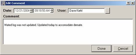
· When reviewing comments, the note is read only but can be selected to be copied and pasted.
Click Done (press Alt+d). You can also click Cancel or press the X in the upper right corner of the window to exit it.
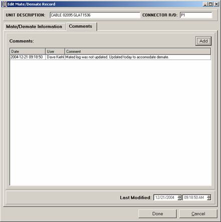
There are three steps you will always need to follow in order to review records in E-Logbook. In particular for the M/D Log:
- In the Main Window HW Mate/Demate tab select a connector from the connector list[9]. The selected connector description and R/D will be shown in the corresponding boxes to the right of the connector list:
- Click on Mate/Demate (press Alt+m)[10]. The M/D Report will appear:
· For properties of the M/D Report window go to section 6.1.2
- Double click on the M/D Record (any of the existing rows in the M/D Report window) you are interested on. The M/D Record window will appear:
- Click Done (press Alt+d) to close the M/D Record window. You can also close this window by clicking Cancel (press Alt+c) or pressing X in the upper right corner of the window.
7. FHW COMPONENT INSTALLATION LOG
This section of ELogbook will teach you to log and visualize information corresponding to the FHW Component Installation Log.
7.1. Create
a FHW Component Installation Record
There are three steps you will always need to follow in order to create records in E-Logbook. In particular for the FHW Component Installation Log:
- Select the FHW Component you want to create a record of.
- Access the FHW Component Report to monitor its current installation state (Install, Remove or In Progress).
- Create the FHW Component Installation Record by clicking add from the report window.
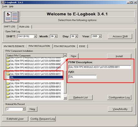
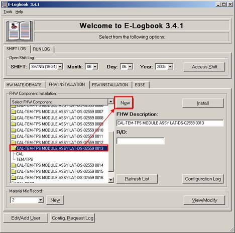
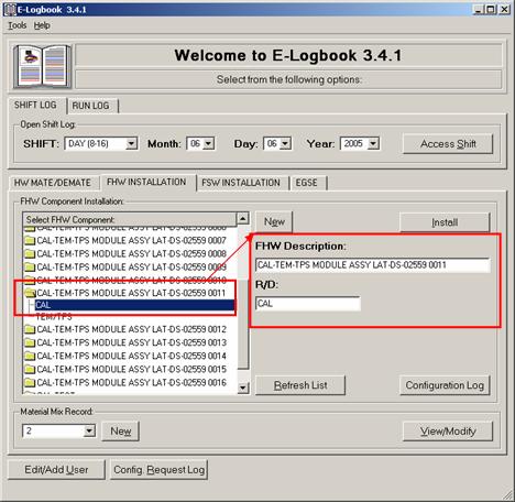
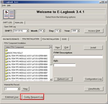
1. In the Main Window FHW Installation tab, select a FHW component from the component list[11]. The selected component description and R/D will be shown in the corresponding boxes to the right of the FHW component list.
7.1.1.1.Create a New FHW Component Record
If the FHW Component you are about to Install is not in E-Logbook you will have to create it:
1. In the Main Window FHW Installation tab tab, make sure that the empty folder is selected in the FHW component list and click New.
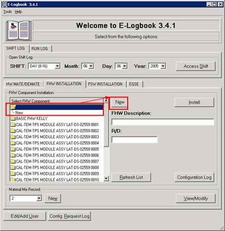
2. The FHW Component Record window will appear:
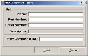
3. Enter the new FHW Component information:
· Name
· Part Number
· Serial Number
These fields will be combined to create the FHW Component Description.
· FHW Component R/D.
4. Click Save. Once you click Save, the new FHW Component will appear in the FHW Component list and in the Description and R/D boxes of the FHW Installation tab.
· Click Cancel (press Alt+c) or press X in the upper right corner of the window to exit at all times without saving the entry.
v To update the FHW Component list in the Main window FHW Installation tab (at all times) click on Refresh List.
You can also create a new R/D for an existing Unit in a quick way:
- In the Main window FHW Installation tab select the Unit Description from the FHW Component list and click New (press Alt+e).
- The FHW Component Record window will appear, this time with the Unit Description already selected:
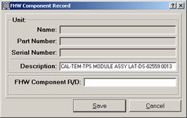
- Enter the new FHW Component R/D.
- Click Save. Once you click Save, the new FHW Component will appear in the FHW Component list and in the Description and R/D boxes of the FHW Installation tab.
· Click Cancel (press Alt+c) or press X in the upper right corner of the window to exit at all times without saving the entry.
v To update the FHW Component list in the Main window FHW Installation tab (at all times) click on Refresh List.
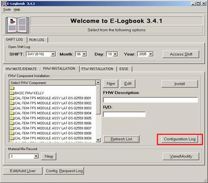
7.1.2. Access the FHW Component Installation Report
- Once the FHW Component has been selected, in the Main window FHW Installation tab click on the Install button (press Alt+i)[12].
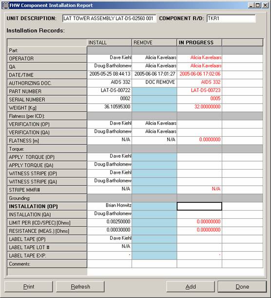
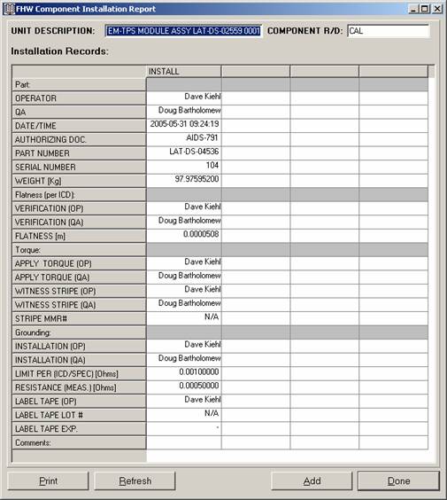
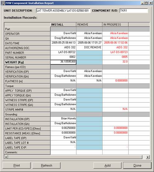
- The FHW Component Installation Report window will appear:
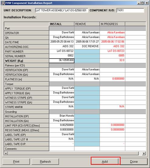
- This window reports the history of all the FHW Installation activities performed on the selected FHW component. Every column is a record and every row is a field. There are as many rows as fields entered during the creation of the record.
- There are three categories:
o Install: Record of a FHW Component installation.
o Remove: Record of a FHW Component removal.
o In Progress: A FHW installation that is in progress.
- It shows if a FHW Installation Record has comments.
- It is printable (click Print (press Alt+p) on the bottom left of the window).
- It can be refreshed (click Refresh (press Alt+r) on the bottom left of the window), to update the list of installation activities performed in the FHW component in the cleanroom at all times.
- You will need to click Add to create a new FHW Installation Record, or double click on a Record (a column in the FHW Component Installation Report) to review it (see the following sections).
7.1.3. Create the FHW Component Installation Record
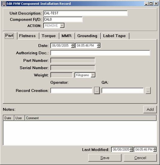
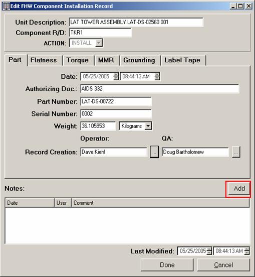
1. In the FHW Component Installation Report click Add (press Alt+a). The Edit FHW Component Installation Record window will appear:
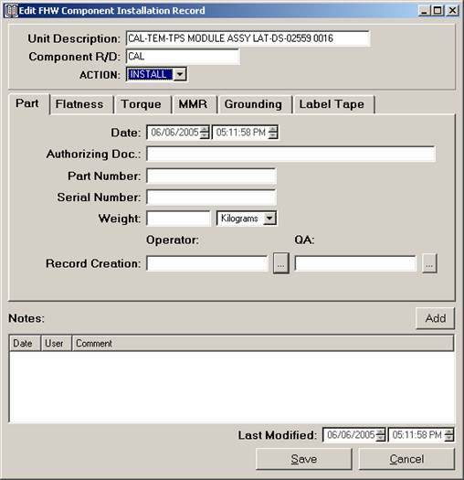
In this window you will log the FHW Component Installation information. There are 6 installation stages (part, flatness, torque, mmr, grounding and tape) identified by the six tabs of the window.
In order to create a record:
· You can fill in the information in stages (the record will appear In Progress (red colored) in the FHW Component Installation Report.
· To save a record In Progress, all the information up to the last stage considered must be entered. The log is not sensitive to the order in which the information is entered as long as ALL the information is entered for every stage up to the last one accomplished.
7.1.3.1. FHW Component Installation Part Stage
In order to create a FHW Component Installation Record you need to fill in AT LEAST the part information.
In order to log the Part stage information:
1. Fill in the following fields:
· Selected FHW component (Description and R/D, given by selection in the Main window).
· Action: Install or Remove.
· Date: The date the record is created, automatically generated by E-Logbook.
· Authorizing Document: The procedure document you are following for the installation or removal.
· Part Number: of the FHW Component.
· Serial Number: of the FHW Component.
· Weight: Enter values only in this field, selecting the units used (IS or English System). You can always toggle later between these units.
2. Operator and QA stamps: must verify EVERY installation stage.
3. Click Save (press Alt+s).
· As long as all the fields corresponding to a certain stage and the QA verification have not been entered, E-Logbook won’t let you save the record.
· Once the record is saved up to a certain stage, all the information entered won’t be modifiable.
· Click Cancel (press Alt+c) or press X in the upper right corner of the window to exit at all times without saving the entry.
Once you click Save, the new FHW Component Installation Record will appear in the FHW Component Installation Report. You can also proceed to fill in the information of the next installation stages instead.
7.1.3.2. FHW Component Installation Flatness Stage
The flatness stage of the FHW Component Installation consists of the flatness verification performed during the installation. If this stage is N/A you will log so as well.
In order to enter the Flatness stage information on a FHW Component Installation record:
1. Select the FHW Component and access its Installation Report following the instructions in the sections above. The current installation will be In Progress and the record will be shown in red:
2. Double click on the record[13]. The Edit FHW Component Installation Record window will appear:
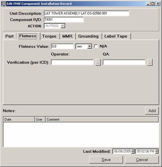
3. Fill in the flatness stage, which consists of the following fields:
· Flatness. Enter values only in this field, selecting the units used (IS or English System). You can always toggle later between these units. If the Flatness value is not applicable click N/A.
4. Operator and QA stamps: must verify EVERY installation stage, even when N/A.
5. Comments: Can be added to a record once it has been created. Click Add above the comments list and follow the instructions in Section 6.2.
6. Click Save (press Alt+s).
· As long as all the fields corresponding to a certain stage and the QA verification have not been entered, E-Logbook won’t let you save the record.
· Once the record is saved up to a certain stage, all the information entered won’t be modifiable.
· Click Cancel (press Alt+c) or press X in the upper right corner of the window to exit at all times without saving the entry.
Once you click Save, the new FHW Component Installation Record will appear in the FHW Component Installation Report. You can also proceed to fill in the information of the next installation stages instead.
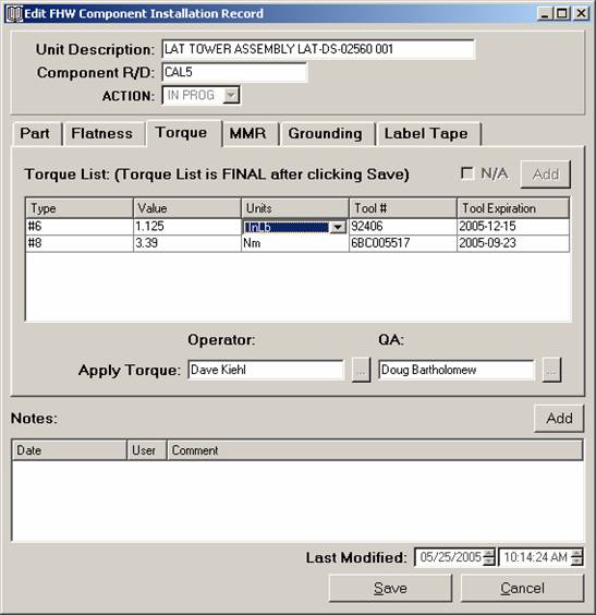
7.1.3.3. FHW Component Installation Torque Stage
The torque stage of the FHW Component Installation consists of all the torques performed during the installation. If this stage is N/A you will log so as well.
In order to enter the Torque stage information on a FHW Component Installation record:
Follow the instructions on the section above to access the record window, but go to the Torque tab:
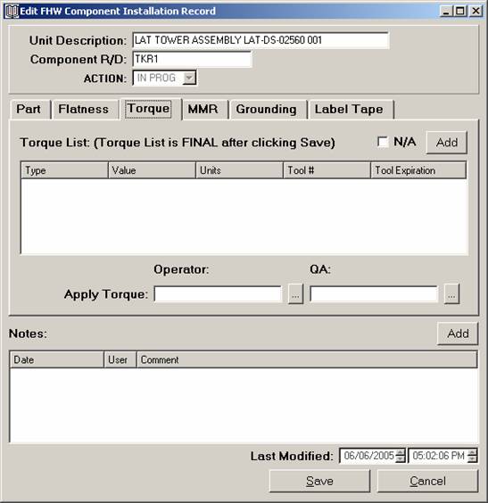
Fill in the torque list: For every torque performed in the FHW Component Installation you will need to create a record in the log. If the Torque stage is not applicable click N/A. In order to enter the torque values:
· Click Add in the Torque tab.
· The Create Torque Record window will appear:

· Enter the torque information:
o Fastener Description.
o Torque Value with the correct units. Enter values only in this field, selecting the units used (IS or English System). You can always toggle later between these units.
o Tool #.
o Tool Expiration.
· Click Save. If any information is missing you will be prompted to enter it. Once all the information has been correctly entered the newly created Torque Record will appear in the Torque List[14] of the FHW Component Installation window.
o Click Cancel (press Alt+c) or press X in the upper right corner of the window to exit at all times without saving the entry.
Operator and QA stamps: must verify EVERY installation stage, even if N/A.
Comments: Can be added to a record once it has been created. Click Add above the comments list and follow the instructions in Section 6.2.
Click Save (press Alt+s).
· As long as all the fields corresponding to a certain stage and the QA verification have not been entered, E-Logbook won’t let you save the record.
· Once the record is saved up to a certain stage, all the information entered won’t be modifiable.
· Click Cancel (press Alt+c) or press X in the upper right corner of the window to exit at all times without saving the entry.
Once you click Save, the new FHW Component Installation Record will appear in the FHW Component Installation Report. You can also proceed to fill in the information of the next installation stages instead:
7.1.3.4. FHW Component Installation MMR Stage
The MMR stage of the FHW Component Installation is the application of any Mix during the installation that will therefore need to be logged. If this stage is N/A you will log so as well in the corresponding record.
In order to enter the MMR stage information on a FHW Component Installation record:
- Follow the instructions on the section above to access the record window, but go to the MMR tab.
2. Select the MMR #, if applicable. Otherwise click N/A. If the MMR has not been created yet click New (press Alt+w) and follow the instructions in Section 8. You can also visualize MMRs by clicking the […] button.
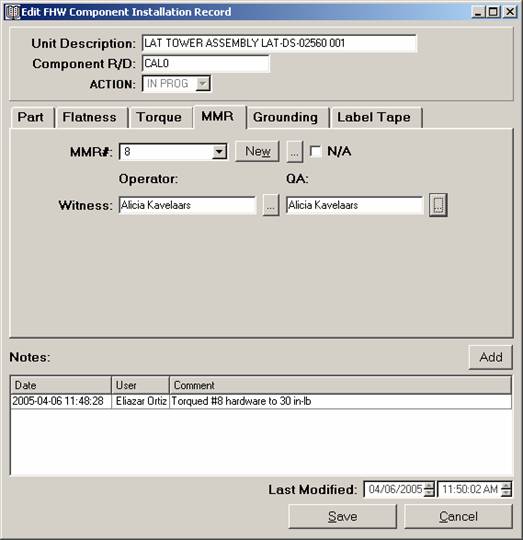
3. Operator and QA stamps: must verify EVERY installation stage, even if N/A.
4. Comments: Comments: Can be added to a record once it has been created. Click Add above the comments list and follow the instructions in Section 6.2.
5. Click Save (press Alt+s).
· As long as all the fields corresponding to a certain stage and the QA verification have not been entered, E-Logbook won’t let you save the record.
· Once the record is saved up to a certain stage, all the information entered won’t be modifiable.
· Click Cancel (press Alt+c) or press X in the upper right corner of the window to exit at all times without saving the entry.
Once you click Save, the new FHW Component Installation Record will appear in the FHW Component Installation Report. You can also proceed to fill in the information of the next installation stages instead:
7.1.3.5. FHW Component Installation Grounding Stage
The Grounding stage of the FHW Component Installation is the verification of the grounding parameters during the installation that will therefore need to be logged. If this stage is N/A you will log so as well.
In order to enter the Grounding stage information on a FHW Component Installation record:
- Follow the instructions on the section above to access the record window, but go to the Grounding tab.
- Fill in the Grounding stage, if applicable. Otherwise click N/A. The Grounding stage fields are:
· Limit Per (ICD/SPEC), in mOhms.
· Resistance, in mOhms. Must be smaller that the Limit Per value.
· Tool #.
· Tool Expiration.
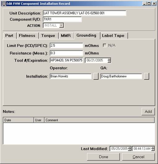
3. Operator and QA stamps: must verify EVERY installation stage, even if N/A.
4. Comments: Comments: Can be added to a record once it has been created. Click Add above the comments list and follow the instructions in Section 6.2.
5. Click Save (press Alt+s).
· As long as all the fields corresponding to a certain stage and the QA verification have not been entered, E-Logbook won’t let you save the record.
· Once the record is saved up to a certain stage, all the information entered won’t be modifiable.
· Click Cancel (press Alt+c) or press X in the upper right corner of the window to exit at all times without saving the entry.
Once you click Save, the new FHW Component Installation Record will appear in the FHW Component Installation Report. You can also proceed to fill in the information of the final installation stage instead:
7.1.3.6. FHW Component Installation Label Tape Stage
The Label Tape stage of the FHW Component Installation is the use of tape to label FHW during the installation that will therefore need to be logged. If this stage is N/A you will log so as well.
In order to enter the Label Tape stage information on a FHW Component Installation record:
- Follow the instructions on the section above to access the record window, but go to the Label Tape tab.
- Fill in the Label Tape stage, if applicable. Otherwise click N/A. The Label Tape stage fields are:
·
Tape
· Tape Expiration.
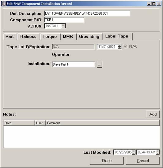
3. Operator and QA stamps: must verify EVERY installation stage, even if N/A.
4. Comments: Can be added to a record once it has been created. Click Add above the comments list and follow the instructions in Section 6.2.
5. Click Save (press Alt+s).
· As long as all the fields corresponding to a certain stage and the QA verification have not been entered, E-Logbook won’t let you save the record.
· Once the record is saved up to a certain stage, all the information entered won’t be modifiable.
· Click Cancel (press Alt+c) or press X in the upper right corner of the window to exit at all times without saving the entry.
Once you click Save, the new FHW Component Installation Record will be successfully finished and will appear in the FHW Component Installation Report as Install in black, (no more In Progress in red):
7.2. Create
a FHW Component Removal Record
There will be instances when FHW Components need to be removed. In order to log a FHW Component removal:
- Select the FHW Component you want to create a record of[15].
- Access the FHW Component Report to monitor its current installation state (Install, Remove or In Progress)[16].
· You can only Remove a FHW Component whose state is Install or In Progress (not Remove).
- Create the FHW Component Installation Record by clicking add from the report window. The current state of the FHW Component will be shown:
- In order to create a FHW Component Removal record you will need to enter the following information:
· Date: The date the record is created, automatically assigned by E-Logbook.
· Authorizing Document: The procedure document you are following for the removal activity.
· Flatness. Enter values only in this field, selecting the units used (IS or English System). You can always toggle later between these units. If the Flatness value is not applicable click N/A.
- Operator and QA stamps: must verify both Part and Flatness removal stages.
6. Click Save (press Alt+s).
· As long as all the fields corresponding to the removal and the QA verification have not been entered, E-Logbook won’t let you save the record.
· Click Cancel (press Alt+c) or press X in the upper right corner of the window to exit at all times without saving the entry.
7. Comments: Can be added to a record once it has been created. Click Add above the comments list and follow the instructions in Section 6.2.
Once you click Save, the new FHW Component Removal Record will be successfully finished and will appear in the FHW Component Installation Report as Removal with the unwanted fields “blued” out:
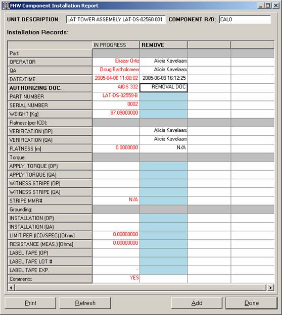
- Click Done (press Alt+d) to close the Report window. You can also close this window by clicking Cancel (press Alt+c) or pressing X in the upper right corner of the window.
7.3. Review
FHW Component Installation Records
There are three steps you will always need to follow in order to review records in E-Logbook. In particular for the FHW Component Installation Log:
- In the Main Window FHW Installation tab, select a FHW Component from the FHW Component list[17]. The selected FHW Component Description and R/D will be shown in the corresponding boxes to the right of the FHW Component list:
- Once the FHW Component has been selected, in the Main window FHW Installation tab click on the Install button (press Alt+i)[18].
- The FHW Component Installation Report window will appear:

· As a reminder (see section 7.1.2), the FHW Component Installation Report is printable (click Print (press Alt+p) on the bottom left of the window).
- Double click on the record you are interested on[19]. The Edit FHW Component Installation Record window will appear:
In this window you will be able to review ALL the information regarding the Installation of a FHW Component.
· Information regarding the 6 installation stages (up to the latest stage logged), or the 2 removal stages.
· Comments entered.
· Last Modified: Timestamp when the record was last modified by adding stage information or comments.
5. Comments: Can be added to a record once it has been created. Click Add above the comments list and follow the instructions in Section 6.2.
- Click Done (press Alt+d) to close the Edit FHW Component Installation Record window. You can also close this window by clicking Cancel (press Alt+c) or pressing X in the upper right corner of the window.
This section of E-Logbook will teach you to log and visualize information corresponding to the Material Mix Record Log.
In order to create a MMR:
- In the Main Window FHW Installation tab go to the Material Mix Record area and click New (press Alt+w).
- The Create MMR window will appear:
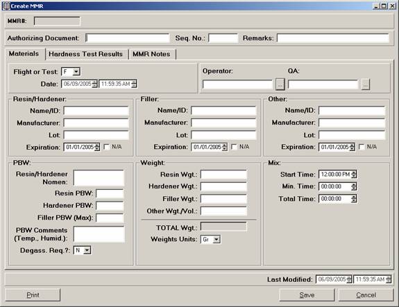
· This window reports all the information related to a certain MMR.
· It is printable (click Print on the bottom left of the window).
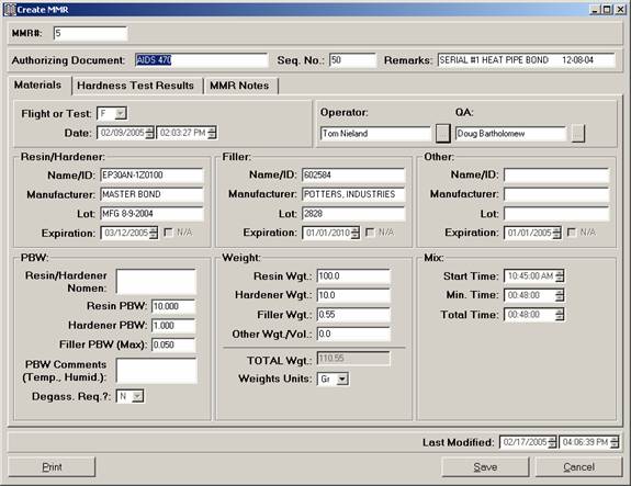
- Enter the following information, where applicable (the fields that must ALWAYS be entered in order to create a MMR show an asterisk *):
· Authorizing Document*: The procedure document you are following for the Material Mix.
· Sequence No*.
· Remarks*: If the Material is only Resin, or Other than Resin/Hardener and Filler. For example if it has been purchased in a pistol and therefore is already mixed.
· Flight or Test hardware*.
· Date*: The date the record is created, automatically generated by E-Logbook.
· Material Information*. For the Resin/Hardener, Filler and Other materials (if applicable, at least one of the three) enter the following information:
- Name/ID.
- Manufacturer.
- Expiration: or click N/A if it is Not Applicable.
· PBWs: Enter the following Part By Weight information, where applicable:
o Resin/Hardener Nomenclature.
o Resin PBW.
o Hardener PBW.
o Filler PBW (maximum).
o Temperature and Humidity at time of data taking.
· Weight values with the correct units (Grams or Ounces)[20] for the materials used, where applicable:
o Resin.
o Hardener.
o Filler.
o Other (Weight or Volume).
o Total (automatically generated by E-Logbook).
· Mix Times: times required to properly mix the materials, where applicable:
o Start Time of mixing.
o Minimum Time required for the materials to be properly mixed.
o Total Time: used to mix the materials (should be always above the minimum time).
- OP and QA stamps*: must verify EVERY stage of the MMR (creation and hardness test result).
5. Click Save (press Alt+s).
· As long as all the necessary fields corresponding to the MMR have not been entered, E-Logbook won’t let you save the record.
· Click Cancel (press Alt+c) or press X in the upper right corner of the window to exit at all times without saving the entry.
Once you click Save, the new MMR will be successfully created and E-Logbook will generate a MMR# and assign it to it. The new MMR# will appear in the MMR list of both the MMR section of the Main window’s FHW Installation tab, and the MMR tab in the FHW Component Installation Record creation window.
A hardness test must be performed on the mix after the indicated time in the MMR procedure document (typically 7 days). To enter the information related to the Hardness Test Result in the MMR Log:
- In the MMR section of the Main Window’s FHW Installation tab select the MMR# from the MMR list and click View/Modify (press Alt+v)[21].
- The Create MMR window will appear:
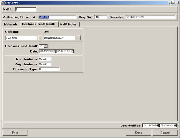
- Go to the Hardness Test Results tab and enter the following information:
· Hardness Test Result: Pass or Fail:
o If the Average Hardness is ABOVE the Minimum Hardness the test has Passed (P).
o If the Average Hardness is BELOW the Minimum Hardness the test has Failed (F).
· Minimum Hardness required by the procedure document.
· Average Hardness achieved.
· Durometer Type.
- OP and QA stamps: must verify EVERY stage of the MMR (creation and hardness test result).
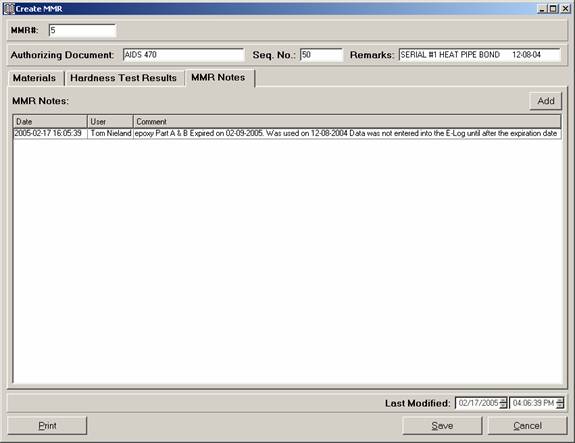
5. MMR Notes: Can be added to a record once it has been created. Click Add above the MMR Notes list in the MMR Notes tab and follow the instructions in Section 6.2.
6. Click Save (press Alt+s).
· As long as all the necessary fields corresponding to the MMR have not been entered, E-Logbook won’t let you save the record.
· Click Cancel (press Alt+c) or press X in the upper right corner of the window to exit at all times without saving the entry.
Once you click Save, the new finished MMR will be successfully updated.
In order to review a MMR:
- In the MMR section of the Main Window’s FHW Installation tab select the MMR# from the MMR list and click View/Modify (press Alt+v)[22].
- The Create MMR window will appear:
In this window you will be able to visualize and perform the following tasks:
· Information regarding the mix and hardness test stages.
· Last Modified: Timestamp when the record was last modified by adding stage information or comments.
· Comments entered.
3. MMR Notes: Can be added to a record once it has been created. Click Add above the MMR Notes list in the MMR Notes tab and follow the instructions in Section 6.2.
- Click Done (press Alt+d) to close the Create MMR window. You can also close this window by clicking Cancel (press Alt+c) or pressing X in the upper right corner of the window.
9. FSW COMPONENT INSTALLATION LOG
This section of ELogbook will teach you to log and visualize information corresponding to the FSW Component Installation Log.
9.1. Create
a FSW Component Installation Record
There are three steps you will always need to follow in order to create records in E-Logbook. In particular for the FSW Component Installation Log:
- Select the FSW Component you want to create a record of.
- Access the FSW Component Report to monitor its current installation state (New Release, Patch, Removal).
- Create the FSW Component Installation Record by clicking add from the report window.
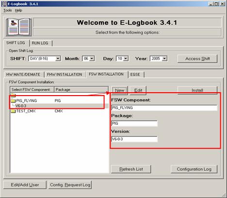
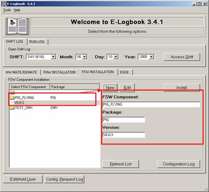
1. In the Main Window FSW Installation tab, select a FSW component from the component list[23]. The selected component Description, Package and Version will be shown in the corresponding boxes to the right of the FHW component list.
9.1.1.1. Create a New FSW Component Record
If the FSW Component you are about to Install is not in E-Logbook you will have to create it:
1. In the Main Window FSW Installation tab, make sure that the empty folder is selected in the FSW component list and click New.
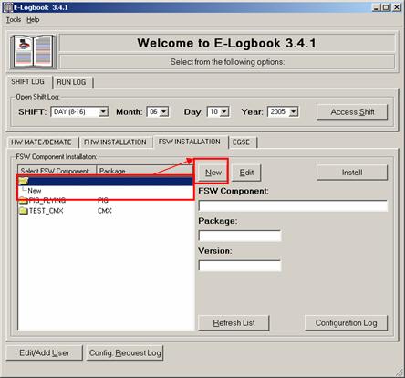
2. The FSW Component Record window will appear:
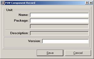
3. Enter the new FSW Component information:
· Name.
· Package of the FSW Component.
These fields will be combined to create the FSW component Description.
· Enter the FSW Version.
4. Click Save. Once you click Save, the new FSW Component will appear in the FSW Component list and in the Component, Package and Version boxes of the FSW Installation tab.
· Click Cancel (press Alt+c) or press X in the upper right corner of the window to exit at all times without saving the entry.
v To update the FSW Component list in the Main window FHW Installation tab (at all times) click on Refresh List (press Alt+r).
You can also create a new Version for an existing FSW Component in a quick way:
1. In the Main window FSW Installation tab select the Unit Description from the FSW Component list and click New (press Alt+e).
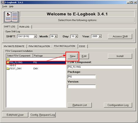
- The FSW Component Record window will appear, this time with the Unit Package and Description already selected:
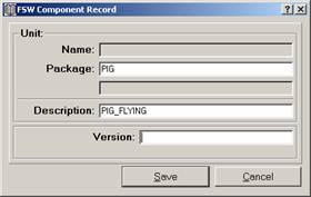
- Enter the new FHW Component Version.
5. Click Save. Once you click Save, the new FSW Component will appear in the FSW Component list and in the Component, Package and Version boxes of the FSW Installation tab.
· Click Cancel (press Alt+c) or press X in the upper right corner of the window to exit at all times without saving the entry.
v To update the FSW Component list in the Main window FHW Installation tab (at all times) click on Refresh List (press Alt+r).
9.1.2. Access the FSW Component Installation Report
1. Once the FSW Component has been selected, in the Main window FSW Installation tab click on the Install button[24].
2. The FSW Component Installation Report window will appear:
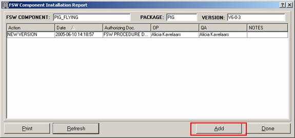
- This window reports the history of all the FSW Installation activities performed on the selected FSW component. Every row is a record and every column is a field. There are as many columns as fields entered during the creation of the record.
- There are three types of actions that can be recorded:
o New Version: Record of a new version installation of the FSW Component.
o Removal: Record of a removal of a version of the FHW Component.
o Patch: Record of a patch of a version of the FHW Component.
- It shows if a FSW Installation Record has comments.
- It is printable (click Print (press Alt+p) on the bottom left of the window).
- It can be refreshed (click Refresh (press Alt+r) on the bottom left of the window), to update the list of installation activities performed in the FSW component in the cleanroom at all times.
- You will need to click Add to create a new FSW Installation Record, or double click on a Record (a row in the FSW Component Installation Report) to review it (see the following sections).
9.1.3. Create the FSW Component Installation Record
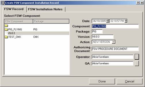
- In the FSW Component Installation Report click Add (press Alt+a). The Create FSW Component Installation Record window will appear:
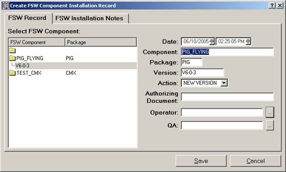
- Log the FSW Component Installation information:
· Date: The date the record is created, automatically generated by E-Logbook.
· Selected FSW component (Description, Package and Version, given by selection in the Main window).
· Action: New Version, Removal or Patch.
· Authorizing Document: The procedure document you are following for the installation.
4. Operator and QA stamps: must verify EVERY record.
5. Click Save (press Alt+s).
· As long as all the fields and the QA verification have not been entered, E-Logbook won’t let you save the record.
· Once the record is saved, all the information entered won’t be modifiable.
· Click Cancel (press Alt+c) or press X in the upper right corner of the window to exit at all times without saving the entry.
Once you click Save, the new FSW Component Installation Record will appear in the FSW Component Installation Report.
9.2. Review
FSW Component Installation Records
There are three steps you will always need to follow in order to review records in E-Logbook. In particular for the FSW Component Installation Log:
1. In the Main Window FSW Installation tab, select a FSW Component from the FSW Component list[25]. The selected FSW Component Description, Package and Version will be shown in the corresponding boxes to the right of the FHW Component list:
2. Once the FSW Component has been selected, in the Main window FSW Installation tab click on the Install button[26].
3. The FSW Component Installation Report window will appear:
![]()
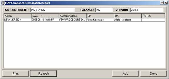
· As a reminder (see section 9.1.2), the FSW Component Installation Report is printable (click Print (press Alt+p) on the bottom left of the window).
4. Double click on the record you are interested on. The Create FSW Component Installation Record window will appear:
In this window you will be able to review ALL the information regarding the Installation of a FSW Component.
· Information regarding the installation or removal.
· FSW Installation Notes entered.
· Last Modified: Timestamp when the record was last modified by adding stage information or comments.
5. FSW Installation Notes: Can be added to a record once it has been created. In the FSW Installation Notes tab click Add above the FSW Installation Notes list. Follow the instructions in Section 6.2.
6. Click Done (press Alt+d) to close the Create FSW Component Installation Record window. You can also close this window by clicking Cancel (press Alt+c) or pressing X in the upper right corner of the window.
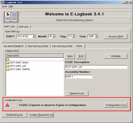
This section of ELogbook will allow you to log and visualize information corresponding to the EGSE Log. The EGSE Log records Electronic Ground Support Equipment Validation activities. In order to create a EGSE record you will need to enter the list of components that comprises the EGSE Unit, as well as global information related to the validation.
10.1. Creating
an EGSE Validation Record
There are three steps you will always need to follow in order to create an EGSE Validation record in E-Logbook:
1. Select the EGSE Component you want to create a record of.
2. Access the EGSE unit Report or Configuration Log (see Section 11 for this Log) to monitor which records have been already created for this unit.
3. Create the EGSE record by clicking add from the report window.
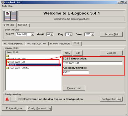
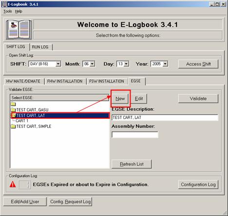
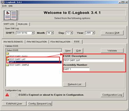
1. In the Main Window EGSE tab, select an EGSE unit from the EGSE list[27]. The selected EGSE Description and Assembly Number/Location will be shown in the corresponding boxes to the right of the EGSE list.
10.1.1.1. Create a New FHW Component Record
If the EGSE Component you are about to Validate is not in E-Logbook you will have to create it:
1. In the Main Window EGSE tab, make sure that the empty folder is selected in the EGSE list and click New (press Alt+n).
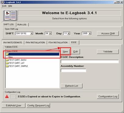
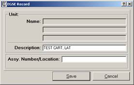
2. The EGSE Component Record window will appear:
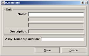
3. Enter the new EGSE Component information:
· Name/ Description.
· Assy. Number; or in case of a Workstation, its location.
4. Click Save. Once you click Save, the new EGSE Component will appear in the EGSE Component list and in the Description and Assembly Number/Location boxes of the EGSE tab.
· Click Cancel (press Alt+c) or press X in the upper right corner of the window to exit at all times without saving the entry.
v To update the EGSE Component list in the Main window EGSE tab (at all times) click on Refresh List (press Alt+r).
You can also create a new Assembly Number/Location for an existing EGSE Component in a quick way:
1. In the Main window EGSE tab select the Description from the EGSE Component list and click New (press Alt+n).
2. The EGSE Component Record window will appear, this time with the Description already selected:
3. Enter the new EGSE Component Assembly Number/ Location.
4. Click Save. Once you click Save, the new EGSE Component will appear in the EGSE Component list and in the Description and Assembly Number/Location boxes of the EGSE tab.
5. Click Cancel (press Alt+c) or press X in the upper right corner of the window to exit at all times without saving the entry.
v To update the EGSE Component list in the Main window EGSE tab (at all times) click on Refresh List (press Alt+r).
10.1.2. Access the ESGE Validation Report
Once the EGSE component is selected in the Main window EGSE tab, you can proceed to access its report. The EGSE Report will list all validation records created on the selected EGSE component thought the lifetime of I&T activities.
To access the EGSE Validation Report:
1. Once the EGSE Component has been selected, in the Main window EGSE tab click on Validate (press Alt+v)[28].
2.
 The
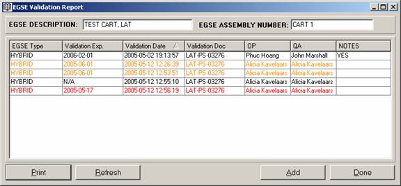
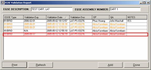
EGSE Validation Report window will appear:
The
EGSE Validation Report window will appear:
- This window reports the history of all the validations performed on the selected EGSE component. Every row is a record and every column is a field. There are as many columns as fields entered during the creation of the record.
- If an EGSE validation record has expired or is about to expire it will be shown with the following color code:
o If a validation is expired it will show in red.
o If a validation is about to expire it will show in orange.
The warning limit (which is 30 days by default) can be customized in the Preferences Menu[29].
- In order to check if an EGSE needs revalidation make sure you browse for the latest record as indicated by the Validation Date. A better tool to monitor record revalidation is the Configuration Log described in Section 11.
- It also shows if an EGSE validation record has comments.
- It is printable (click Print (press Alt+p) on the bottom left of the window).
- It can be refreshed (click Refresh (press Alt+r) on the bottom left of the window or click F5), to update the list of validation activities performed in the EGSE component in the cleanroom at all times.
- You will need to click Add to create a new EGSE Validation Record, or double click on a Record (a row in the EGSE Validation Report) to review it (see the following sections).
10.1.3. Create the EGSE Validation Record
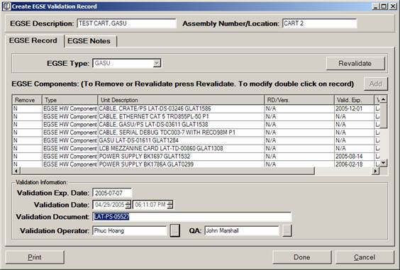
1. In the EGSE Validation Report click Add (press Alt+a). The Create EGSE Validation Record window will appear:
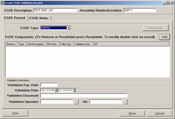
- Log the EGSE Validation information:
· Selected EGSE component (Description and Assembly Number/ Location, given by the selection in the Main window).
· EGSE Type: GASU, SIMPLE, LAT, HYBRID (if two EGSE assemblies are coupled together to create a new EGSE).
· EGSE Components (see next section). Enter as many EGSE Component records as necessary.
· Validation Expiration Date: automatically generated by E-Logbook as the earliest Validation Expiration Date in the list of EGSE Components entered.
· Validation Date: The date the record is created, automatically generated by E-Logbook.
· Validation Document: The procedure document you are following for the validation.
6. Operator and QA stamps: must verify EVERY record.
7. Click Save (press Alt+s).
· As long as all the fields and the QA verification have not been entered, E-Logbook won’t let you save the record.
· Once the record is saved, all the information entered won’t be modifiable.
· Click Cancel (press Alt+c) or press X in the upper right corner of the window to exit at all times without saving the entry.
Once you click Save, the new EGSE Validation Record will appear in the EGSE Validation Report and Configuration Log.
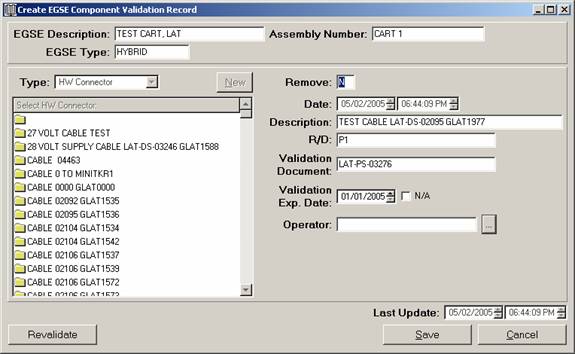
1. In the Create EGSE Validation Record window click Add (press Alt+a). The Create EGSE Component Validation Record window will appear:
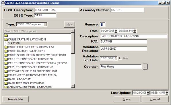
2. Log the EGSE Component Validation information:
· EGSE Component Type:
o HW Connector.
o FHW Component.
o EGSE HW Component.
o EGSE SW Component.
o EGSE (for Hybrid EGSE that are created from other EGSE assemblies).
· EGSE Component: Select it from the list. If the Component is not in the corresponding list click New (press Alt+n) and follow the instructions in sections 6.1.1. (HW Connector Type), 7.1.1. (FHW Component Type) or 10.1.1 (EGSE Type – for Hybrid Records).
o Typically for the EGSE HW and SW Component Lists the EGSE Component needs to be added to the list. If you need to add an EGSE HW Component the EGSE HW Component Record window will appear:
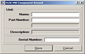
§ Enter the Name, Part Number and Serial Number information.
o If you need to add an EGSE SW Component the EGSE SW Component Record window will appear:
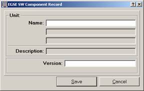
§ Enter the Name and Version information.
· Remove: Yes or No, if the record has been selected for removal (only applies to revalidation). Automatically generated by E-Logbook.
· Date: The date the record is created, automatically generated by E-Logbook.
· Selected EGSE Component (Description and R/D/Assembly Number/ Location, given by the selection from the EGSE Type list).
· Validation Document: The procedure document followed for the component validation.
· Validation Expiration Date, or click N/A if Not Applicable (for example for EGSE SW Components).
8. Operator stamp: must verify EVERY EGSE Component record.
9. Click Save (press Alt+s).
· As long as all the fields have not been entered, E-Logbook won’t let you save the record.
· Click Cancel (press Alt+c) or press X in the upper right corner of the window to exit at all times without saving the entry.
Repeat this operation as many times as records are needed for all the EGSE Components in the unit you are about to validate.
10.2. Review EGSE
Validation Records
There are three steps you will always need to follow in order to review records in E-Logbook. In particular for the EGSE Validation Log:
- In the Main Window EGSE tab, select an EGSE unit from the EGSE list[30]. The selected EGSE Description and Assembly Number/Location will be shown in the corresponding boxes to the right of the EGSE list.
- Once the EGSE Unit has been selected, in the Main window EGSE tab click Validate (press Alt+v)[31].
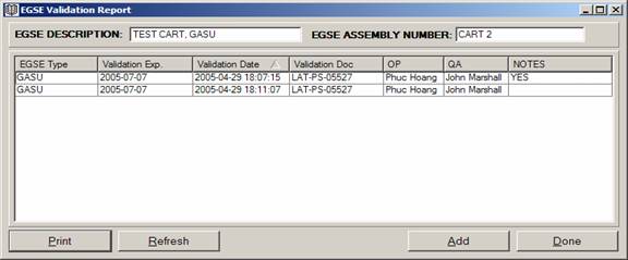
- The EGSE Validation Report window will appear:
· If an EGSE validation record has expired or is about to expire it will be shown with the following color code:
- If a validation is expired it will show in red.
- If a validation is about to expire it will show in orange.
The warning limit (which is 30 days by default) can be customized in the Preferences Menu[32].
· As a reminder (see section 10.1.2), the EGSE Validation Report is printable (click Print (press Alt+p) on the bottom left of the window).
- Double click on the record you are interested on. The Create EGSE Validation Record window will appear:
 In
this window you will be able to review ALL the information regarding the validation
of an EGSE Unit.
In
this window you will be able to review ALL the information regarding the validation
of an EGSE Unit.
· You can click Print (press Alt+p) to print the EGSE Validation Record.
· Last Modified: Timestamp when the record was last modified by adding EGSE Notes.
5. EGSE Notes: Can be added to a record once it has been created. In the EGSE Notes tab click Add above the EGSE Notes list (follow the instructions in Section 6.2).
6. Click Done (press Alt+d) to close the Create EGSE Validation Record window. You can also close this window by clicking Cancel (press Alt+c) or pressing X in the upper right corner of the window.
For EGSE Units that have expired or are about to expire validation you will need to revalidate their record information in E-Logbook. In order to revalidate EGSE you can create a new Validation Record from scratch, or better if possible revalidate an existing record by updating the existing information.
To revalidate an EGSE:
1. Select an EGSE and access the EGSE Validation Report. Select the latest EGSE Validation record; or
Access the EGSE Configuration Log and select the EGSE Unit you wish to revalidate (by definition only the latest record of each unit will be displayed in the Configuration Log - see section 11).
Once you access the EGSE Validation Record click on Revalidate. This will enable all the fields for update.
Update/revalidate the EGSE Record information:
· EGSE Type.
· EGSE Components: There are several ways you can do this:
You can click the Add button in order to add more EGSE Components to the list.
You can double click on an existing component in order to update its information (see next section).
You can Add/Remove a Component by selecting Yes or No from the drop down list in the Remove column[33].
· Validation Document.
Operator and QA stamps: must verify EVERY EGSE Component record.
Click Save (press Alt+s).
· As long as all the fields have not been entered, E-Logbook won’t let you save the record.
· Once the record is saved, all the information entered won’t be modifiable.
· Click Cancel (press Alt+c) or press X in the upper right corner of the window to exit at all times without saving the entry.
Once you click Save, the new EGSE Validation Record will appear in the EGSE Validation Report and Configuration Log.
v You can also revalidate from an EGSE Validation Record other than the latest in the EGSE Validation Report if it contains a more convenient list of EGSE Components and Validation Expiration Dates.
10.3.1. Revalidate EGSE Components
You can revalidate EGSE Components by updating their information. To revalidate an EGSE Component Record:
On the EGSE Component List double click on an existing EGSE Component Record.
The EGSE Component Validation Record window will appear:
Click on Revalidate. The following information will be enabled for update:
· Validation Document.
· Validation Expiration Date.
Operator stamp: must verify EVERY EGSE Component record.
Click Save (press Alt+s).
· As long as all the fields have not been entered, E-Logbook won’t let you save the record.
· Click Cancel (press Alt+c) or press X in the upper right corner of the window to exit at all times without saving the entry.
Repeat this operation as many times as needed for all the EGSE Components in the unit you need to revalidate.

By definition the Configuration
Log reports a current snapshot of all the components currently installed or
validated in E-Logbook. It is therefore a useful list of the
There are three configuration Logs in E-Logbook:
- FHW Configuration Log.
- FSW Configuration Log.
- EGSE Validation Configuration Log.
11.1. Reports
versus Configuration Logs
There is a major difference between Component Reports and Configuration Logs:
·
Component
Reports: Are lists of all records created for A CERTAIN Component.
·
Configuration
Log: Are lists of the LAST record ALL Components. The configuration log is
a snapshot of the
11.2. Access the
Configuration Logs
- In the Main Window FHW Installation, FSW Installation or EGSE tabs, click the Configuration Log Button (press Alt+o):
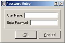
- Fill in the username and password window to log the Configuration Log request. The requests can be monitored in the Configuration Request Log (see Section 12):
- The FHW Installation, FSW Installation or EGSE Configuration Log window will appear:
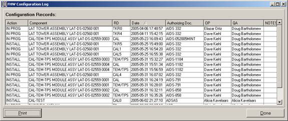
· The Configuration Log is printable (click Print (press Alt+p) on the bottom left of the window).
- If you would like to further investigate a certain record, double click on the row you are interested on and the FHW, FSW or EGSE creation window will appear.
· In this window you will be able to review ALL the information regarding the Installation of a FHW or FSW Component, or the Validation of an EGSE Component (for further information go to Sections 7.3, 9.3 or 10.3).
- Click Done (press Alt+d) to close the windows. You can also close this window by clicking Cancel (press Alt+c) or pressing X in the upper right corner of the window.
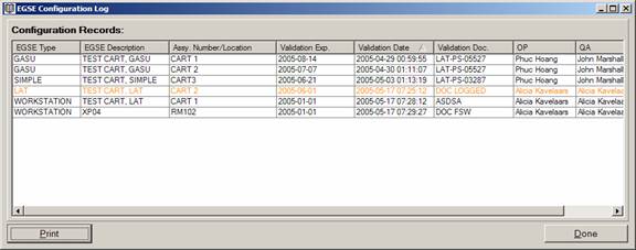
11.3. The EGSE
Configuration Log
The Configuration Log is especially useful for the EGSE Log since it allows you to monitor which EGSE Units have expired or are about to expire configuration, as well as access the EGSE Records for revalidation. There is an extra glance tool in the EGSE tab for fast monitoring of EGSE record expiration:
11.4. CONFIGURATION
REQUEST LOG
The Configuration Request Log is a list of all the user requests for Configuration Logs throughout the lifetime of the I&T activities.
To access the Configuration Request Log:
- In the Main Window click the Configuration Request Log Button:
- The Configuration Request Log will appear:
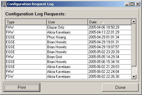
- In this window you will monitor following information:
Type: of Configuration Log requested (FHW, FSW or EGSE).
User: that requested it.
Date: The date the Configuration Log was requested, automatically generated by E-Logbook.
- Click Print (press Alt+p) to print the Configuration Request Log.
- Click Done (press Alt+d) to close the Configuration Request Log window. You can also close this window by pressing X in the upper right corner of the window.
If you have any questions, please contact:
Alicia T. Kavelaars aliciak@SLAC.Stanford.edu
Ric Claus claus@SLAC.Stanford.edu
Or visit the E-logbook website @
http://www-glast.slac.stanford.edu/IntegrationTest/ONLINE/ELogbook/index.htm
We would love to hear your input and new ideas on how to improve E-Logbook.