The Standard Environment for the Analysis of LAT Data
v10 (Monday, Sept 16, 2002)
1 Introduction
1.1 Purpose
This document describes the environment in which data from the LAT instrument on GLAST will be analyzed, the process by which this environment was defined, and the methods by which it will be developed. The contents of this document were developed by the SSC-LAT Software Working Group. Because the feasibility of implementing various analysis algorithms will be the subject of trade studies and computer technology will advance in the years until the launch of GLAST, the design of the analysis environment will evolve. Nonetheless, here we outline our understanding of the tools necessary to analyze LAT data and our concept of how the user community will be served.
This document was prepared with the assumption that the reader is familiar with standard GLAST mission and LAT instrument terminology. Appendix A defines some of the most important terms.
1.2 The User Communities
Two communities will analyze LAT data, each with its own needs. LAT team members are clustered at a number of institutions in different countries. Many in this community will presumably be heavy users of the LAT data, and thus LAT team members will be able to turn to colleagues both at their own institutions and on the instrument team for assistance in analyzing the LAT data and using the analysis tools. The LAT IOC will provide the LAT team with LAT Level 1 data. LAT team members may use the analysis tools on the same servers on which the databases are located, or the databases may be cross-mounted on the analysis computers; computational, storage, and data retrieval bandwidth limitations may not be as severe as for individual guest investigators.
We envisage the typical member of the general astrophysical community to be an investigator analyzing LAT data independent of the LAT instrument team, using the desktop computer generally available at the time of the launch of GLAST. Note that by Moore’s Law, at the beginning of Phase 2 the average desktop computer will be ~10 times more powerful than current computers! Most of these investigators will have had experience analyzing high energy astrophysics data. The GLAST Science Support Center (SSC) at Goddard will make available both data and analysis tools to this community. The Level 1 data for this community will reside on the SSC’s servers. The user will extract data from the SSC’s databases, and export the resulting data files back to his/her home institution over the internet. Thus the distinction between the central server and the user’s computer is relevant.
Because the SSC (and the LAT instrument team) will not have the resources to assist users individually, the analysis tools and their interface must be robust enough to withstand the use of relatively unsophisticated users. The documentation must be sufficient for an investigator to learn quickly and easily how to perform standard types of analysis. GLAST will be most successful if investigators who do not specialize in LAT analysis will feel that the LAT data are accessible.
1.3 The Challenges of Analyzing LAT Data
Analyzing LAT data will be challenging. The point spread function (PSF) at high energies will be fairly small (~0.15°) but at low energy (where most of the photons will be detected) the PSF will be quite large (~3.5°). Because of the LAT’s greater sensitivity relative to EGRET, many more weak sources will be detected. At low energy it will be difficult to disentangle the different sources. Therefore, the analysis of even a point source is inherently multi-dimensional: spatial, spectral and temporal. The EGRET data were analyzed as a series of two dimensional maps in different energy bands accumulated over a time range; we hope to perform true multi-dimensional analysis.
Almost all the data will be accumulated while GLAST surveys the sky; even during “pointed observations” the field-of-view (FOV) will drift. Consequently, each photon will be detected at a different orientation between the source and the detector normal; a different instrument response applies to each photon. Even with the LAT’s greater effective area relative to EGRET, the data space (e.g., apparent energy, apparent origin on the sky, orientation to the LAT) will be large and sparsely populated with detected photons.
The LAT’s FOV will be extremely large (>2 sr), and GLAST will usually scan the sky. Therefore exposure will be built up in ~30 minute chunks every orbit, not continuously. Exposure to a given source will build up more slowly in this survey mode than for pointed observations. Even with a large effective area, the photon detection rate of the LAT will make the detection of pulsars known at other wavelengths very sensitive to the pulsar ephemeris. The exposure will be accumulated at a variety of orientations of the LAT relative to sources of interest, resulting in a variable effective area; GLAST’s observing modes will introduce a window function that will complicate the analysis of periodic sources such as pulsars.
Consequently, the science tools must implement sophisticated data analysis techniques (e.g., likelihood methods for sparsely-populated, multidimensional data spaces) if the LAT’s full potential is to be realized. The development of these tools will entail trade studies to determine what methods will be feasible given the computational resources available to the average investigator.
1.4 Responsibilities of the LAT Instrument Team and the SSC For the Definition and Development of the Standard Analysis Environment
The Announcement of Opportunity (AO) for GLAST’s instruments stated that the instrument teams are responsible for the “production of data analysis software” and the SSC for the “generation of high-level data analysis tools” (AO, p. 10). While LAT scientists will actively develop analysis tools, the team does not have sufficient resources to create a robust analysis environment for the general community. Conversely, SSC scientists are intellectually stimulated by the complexity of the LAT data analysis, will be engaged in the science that will result, and must be intimately familiar with the analysis tools provided to the community the SSC will support; consequently SSC scientists are willing and eager to participate in the development of these tools. Since the SSC is responsible for making possible the analysis of GLAST data by the general scientific community, the SSC has a keen interest in the completeness of the suite of analysis tools available at launch.
Consequently it was agreed that the LAT team and the SSC will jointly define the science tools and the environment in which they will be used, the LAT team will be responsible for managing the development of the science tools, and SSC scientists and programmers will participate in the development effort. There is a formal understanding that the tools have to serve the general scientific community; for example, this dictates the use of FITS format files.
To implement this division of labor and responsibilities the SSC-LAT Software Working Group was established. Meeting weekly by VRVS teleconferencing, the working group consists of Toby Burnett, Seth Digel (co-chair), and Richard Dubois from the LAT team and David Band (co-chair), Jay Norris and Bob Schaefer from the SSC. The working group has been concerned with the definition of the tools, the architecture of the relevant databases (particularly the event database), the software environment and the Level 1 pipeline. Once software is developed this working group will oversee the review the resulting tools to determine whether they satisfy the requirements for the analysis environment.
A detailed management plan is presented in §5.1.
1.5 The Process of Defining the Standard Analysis Environment
The definition of the standard analysis environment (SAE) is based on experience with EGRET and other high energy astrophysics missions, the scientific goals for the LAT described in the GLAST Science Requirements Document, developments in software technology, and analysis of the challenges posed by LAT data. Identification of the analysis tools needed to support LAT data analysis began in earnest in January, 2000, with a LAT software workshop at SLAC. The definition of the SAE presented here is an extension of that initial work, more complete and considerably refined. Once the strong role of the SSC in the development of the high-level analysis software for the LAT was clarified (§1.4), the definition of the analysis environment described here was undertaken as a joint effort overseen by the SSC-LAT Software Working Group.
The analysis environment was defined with the needs and requirements of the LAT team and guest investigator communities in mind. Many of these requirements are stated in the GLAST Mission System Specification (MSS). On the most basic level, this environment will "provide validated science data to the GLAST user community." (MSS 3.1.2.6) It will provide a "single higher-level analysis software environment for use by the community and by the instrument teams" (MSS 3.5.1.4) and will "respect standards that ensure software portability, independence of vendor, and compatibility with existing multi-mission high-energy astrophysics tools." (MSS 3.5.1.5) The system is constructed to "interface with the High Energy Astrophysics Science Archive Research Center (HEASARC) in support of multi-wavelength studies." (MSS 3.5.3.4). A key aspect of the compatibility with the existing high energy astrophysics infrastructure is the use of FITS format files, with HEASARC-defined keywords. Finally, the analysis environment will "interface with GLAST investigators via the commercial internet" and will "provide access to GLAST data that is made public via the commercial internet." (MSS 3.5.3.5)
The definition process has been iterative and driven by use cases that describe specific analysis tasks and how they could be performed. Therefore, the tools on the SAE are well matched to the scientific goals specified in the GLAST Science Requirements Document, including: determine the positions and fluxes of blazars (SRD §2.1), analyze the spectral and temporal properties of GRBs (SRD §2.3), study small extended sources like molecular clouds (SRD §2.5), analyze the timing and spectral properties of gamma-ray pulsars (SRD §2.6), and perform periodicity searches and search for counterparts of unidentified sources (SRD §2.7). Contributions have come from within the SSC-LAT working group, the SSC and the LAT and GBM instrument teams. The SAE presented here was the topic of a 3-day workshop at SLAC in June 2002 with broad representation from the LAT collaboration and the SSC (approximately 30 attendees in total). The workshop included consideration of the definitions of the analysis tools as well as the software development environment, the management plan, and considerations for defining the development schedule.
In defining the SAE, we have primarily considered the requirements for each of the components, but we have also tried to identify areas where implementation considerations are the greatest. For many of the components of the analysis environment, the approach to implementation is clear, either because the algorithm is well known from other high-energy astronomy mission analysis systems, or from the limited scope of the tool. For some components, in particular databases and the core interactive analysis tools, the best approach is not as clear. We have identified potential options for their implementation and included time in the development schedule for prototyping them.
1.6 Scope of the analysis environment
The purpose of the analysis environment defined here is to enable the general scientific community to extract astrophysical results from the LAT Level 1 data. Thus the environment assumes the existence of lists of “photons” from the LAT, and does not concern itself with the analysis of tracks in the LAT (event reconstruction and classification) that results in the parameters of the photons.
In addition, the SAE does not include the specialized tools that would be required to address some of the scientific goals for the LAT, for example tools to construct the interstellar emission model, derive the point source catalog, detect transients (both topics assigned to the LAT team), search for particle annihilation lines from the Galactic Center, or study solar flares or cosmic rays. For these topics and no doubt others that we have not yet imagined, the LAT team and guest investigators will have to write their own software. Because the SAE does have a wide scope and flexible tools for model definition (e.g., some aspects of solar flares could be studied with the GRB tools), our expectation is that only a small fraction of the community will need additional tools. We plan to make contributed software available to the community after proper vetting.
2 Components of the analysis environment
In this section we introduce the SAE, with emphasis on the components of the environment and their interrelations. Complete specifications of the tool and databases that constitute the SAE are provided in Appendix C. In what follows, the components are identified by their designations (D for database, U for utility, A for analysis tool, O for observation simulation, and UI for user interface, followed by number that we have assigned) as they are discussed. The distinction in designation between analysis tools and utilities is somewhat subjective; the intention is that tools designated as utilities produce output needed by analysis tools, including providing interfaces to the databases.
2.1 Event data, pointing & livetime history, and response functions
As stated in §1, the SAE is intended for astrophysical research with LAT data. The principal inputs are already-processed (Level 1) event data, LAT pointing and livetime information, and the instrument response functions that provide the high-level characterization of the LAT (Fig. 2.1). The event data are assumed to have charged particle backgrounds (events recorded in the LAT due to the passage of cosmic rays) eliminated and gamma rays characterized by event class, energy, time, and direction in celestial coordinates (D1). Event class can be considered a set of flag values that indicate the quality of the energy and direction determinations. The pointing and livetime history (D2) is needed to calculate exposures, and ultimately calibrated fluxes. The response functions (D3) are used in most high-level analyses, to permit comparison of models for gamma-ray distributions with observations.
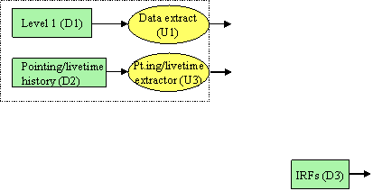
Figure 2.1
D1 and D2 will have implementations that are specific to the LAT (for example, the event data in D1 may be stored as spatially indexed database tables in a relational database system). For long-term maintenance of the analysis tools in the post-mission era, and in general to make the analysis tools independent of the implementation of the database system, D1 and D2 will be accessed only by utilities U1 and U3. These will format the requests, e.g., construct database queries, as well as translate the output to FITS format, if it is not already. By agreement with the HEASARC the analysis tools will read and write FITS format files compatible with the OGIP (Office of Guest Investigator Programs) standard. Also by agreement with the HEASARC, D3 will be implemented in CALDB, the HEASARC-defined system of indexed FITS files for representing instrument response functions. (See the detailed description of D3 in Appendix C). As no translation of D3 for the post-mission era of maintenance by HEASARC is foreseen, we do not define a special intermediary utility for accessing D3.
2.2 Event display
The SAE does include a facility for viewing the low-level information – the pattern of hits in the tracker, energy depositions in the calorimeter logs, and hit tiles in the anticoincidence detector, along with the assignments of hits to tracks and the parameters derived for event classification – for an event. The provision of an event display tool (UI1, Fig. 2.2) is not to provide an analysis step that relates to other parts of the SAE, but instead transparency, literally a window into the lower-level processing that results from the SAE will be built on. In many instances, for examples for GRBs detected by the LAT, new results will hinge on one or a few gamma rays, and the event display will permit investigators to judge quality for themselves.
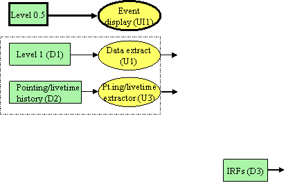
Figure 2.2
2.3 Exposure
The calculation of exposure (U4, Fig. 2.3) requires the pointing and livetime history, as mentioned above, as well as the instrument response functions (D3). These represent the high-level response of the LAT, in terms of its effective area, energy resolution, and point-spread function as functions of the gamma-ray arrival direction (in instrument coordinates), its energy, and other parameters. The exact set is still to be determined but may include plane (or tower) of conversion and event class (a kind of quality flag for energy and direction determinations and an indication of which background rejection cuts the event passes). If the response of the LAT changes on orbit, e.g., in response to a hardware failure, the instrument response functions will need to be updated, and will therefore become time dependent. A utility for extracting and displaying response functions is provided in the SAE (U10).
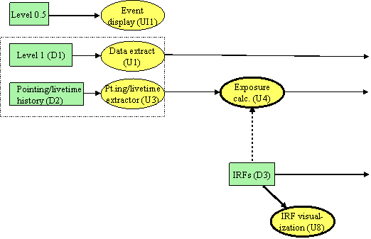
Figure 2.3
In Figure 2.3, the connection between the IRFs (D3) and the exposure calculation is indicated as a dotted line because U4 may actually be implemented to factor out the instrument response (effective area) from the livetime accumulation. Although the effective area is certainly part of the exposure, factoring the calculation in this way may have several implementation advantages. See the discussion in the Open Issues section of the requirements summary for U4 in Appendix C for more information.
2.4 Likelihood analysis
The standard analysis of LAT data will be via model fitting, owing to the limited numbers of gamma rays, the relatively poor angular resolution of pair conversion telescopes, and the pervasiveness of structured diffuse gamma-ray emission from the Milky Way. (Approximately 60% of the gamma rays that EGRET detected were diffuse emission from the Milky Way.) The SAE includes an interstellar emission model (U5, Fig. 2.4) that describes the spectral distribution of the emission across the sky. The model will likely have some adjustable parameters, perhaps related to the Galactic cosmic-ray distribution, that will be optimized in the model fitting analysis. (U5 will be updated at least once based on analysis of LAT data, and the adjustable parameters may either be fixed or have recommended values specified as a result.)
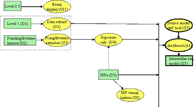
Figure 2.4 (To reduce the complexity of the diagram, tools that require the same set of inputs as each other are drawn showing the inputs connecting to a common vertical bar, and the tools individually connect to the vertical bar.)
The workhorse analysis tool in the SAE is the model fitting tool (A1, Fig. 2.4). As for other high-energy gamma-ray astronomy missions, for the LAT we expect that the model fitting tool will implement maximum likelihood analysis. For the SAE we envision a flexible tool (U7) for defining models to be analyzed with A1. The likelihood analysis (described more fully in the use cases in §4) can be used to detect gamma-ray point sources and characterize their positions, fluxes, and spectra. U7 will allow specification of extended sources as well, small angular size diffuse sources that the LAT may resolve. As defined for the SAE, A1 analyzes data for finite intervals of time, fitting models that are static (for the time interval analyzed). Analyses of data for successive time intervals can be used to monitor for flaring gamma-ray sources.
2.5 Point source catalog, astronomical catalogs, and source identification
Supporting the high-level analysis of point sources will be tools to access the LAT point source catalog (D5, the initial version of which will be based on the LAT sky survey data; Fig. 2.5), and catalogs of astronomical sources useful for counterpart identifications (D6, e.g., flat spectrum radio sources or X-ray sources). These will be available both to the source model definition tool (U7) and to a source identification tool (A2), which will evaluate probabilities of chance coincidences between gamma-ray sources and those in other catalogs. A2 will rely on properties of the catalogs – flux distributions, coverages, etc., in deriving the probabilities.
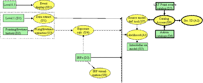
Figure 2.5
2.6 Pulsar analyses
All of the routine analysis of point sources can be carried out for pulsars as well, with optional selection of data based on pulsar phase. During the mission, radio timing observations of known and candidate gamma-ray pulsars will be undertaken (by a GLAST project-supported effort) to produce a database of pulsar ephemerides (D4, Fig. 2.6). The utilities U11, U10, and U12 will extract timing information for the desired pulsar, correct the gamma-ray arrival times to the solar system barycenter, and then calculate pulsar phases. This information will be appended to the gamma-ray event data extracted from D1. The phase assignment is separate from the arrival time correction to facilitate export of pulsar data from the SAE. The likelihood analysis tool (A1) and the map generation utility (U6, discussed below) will optionally accept specification of pulsar phase ranges for their analyses and map generation and will scale the exposures appropriately.
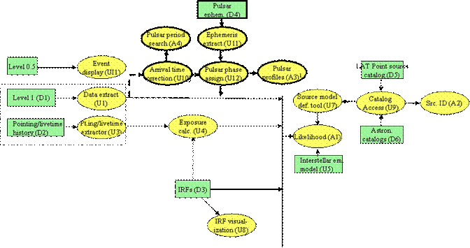
Figure 2.6
Searches for periodic emission using the ephemeris of a known pulsar will be possible with U2 and A3. U2 applies an energy-dependent selection cut (narrower at greater energies) to the event data around the position of the pulsar to maximize the pulsed signal. Then A3 is used to phase fold the resulting gamma rays and apply statistical tests for periodicity. It can also search narrow ranges of frequency, in case the radio ephemeris is not quite accurate.
For bright unidentified sources, with many gamma rays, the pulsar period search tool (A4) can search for periodic gamma-ray emission. The process is very computation intensive, but standard algorithms are well understood. Indeed the Geminga class of gamma-ray pulsars that have no periodic radio emission is expected to grow greatly (as a result of successful searches for gamma-ray periodicity) with the increased effective area and angular resolution of the LAT.
2.7 Map generation
The map generation utility (U6, Fig. 2.7) will generate gamma-ray, exposure, and intensity maps for user-specified regions of the sky, time ranges, energy ranges, and other sets of parameters, such as event class and zenith angle cuts [mention with exposure calculation]. The likelihood analysis itself will not be map based, or at least not based on single maps of the sky, owing to the scanning mode of operation of the LAT together with its large field of view and significant variation of IRFs across the field of view. Binning the data into maps on the sky (as U6 will do) will be useful for visual inspection, and export, of the data, but will generally result in the loss of useful information for quantitative analysis with the likelihood tool.
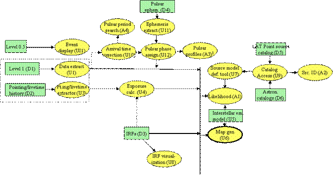
Figure 2.7
2.8 Gamma-ray bursts
A comprehensive set of GRB analysis tools is included in the SAE (Fig. 2.8). Most of the tools will have multi-instrument (e.g., LAT, GBM, Swift, and Integral) data analysis capabilities. The analysis tools can be used for either LAT or GBM data, although here we present only the instrument response-related tools for the LAT; similar tools for the GBM will be treated elsewhere. Bursts will be localized by the instrument teams in their standard response to the detection of a burst, although users will be able to localize bursts using the standard likelihood analysis tool A1. The tools that specialize in GRB analysis take advantage of the bright, transient nature of bursts for study of their temporal profiles and spectra in the regime where celestial backgrounds can be neglected for the LAT data.
The SAE includes an interactive visualization tool (U13) for display of binned data as counts spectra or time profiles, or unbinned data to provide visual assessment of bursts, their pulses and spectral evolution. The analysis tools will provide similar graphical displays to assist the user.
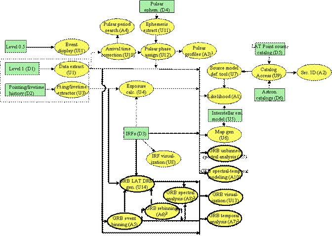
Figure 2.8
Binned spectral analysis will suffice for bright GRBs for which many LAT photons are detected. For this analysis the data are binned in time and apparent energy. The analysis path for these bursts proceeds via binning the data (A5; A6 rebins data that are already binned), generating the DRMs (Detector Response Matrices, versions of the instrument response functions for one dimensional spectra) appropriate to the spectra's time and energy bins (U14), then fitting spectral models via an XSPEC-like tool (A8). We anticipate that joint fits to the LAT and GBM data will be standard. Alternatively, the temporal profiles can be analyzed using A7, which is also planned to be able to utilize unbinned event data (selected for a the time range of a GRB and a suitably large region of the sky).
For GRBs with fewer photons unbinned spectral analysis will be required. For this analysis the data are binned in time but not in apparent energy. Although this tool (A9) will be based on likelihood methods similar to the general likelihood tool A1, the spectra will be unbinned in only one dimension and will involve only a few events; consequently the GRB tool will use computational techniques that cannot be applied in the A1 tool, e.g., using analytic derivatives of the spectral models to maximize the likelihood. Since the spectral models will be simple and the region around the burst will not be modeled spatially, the standard model definition utility is unnecessary. The instrument response required for this analysis will be generated by the standard exposure tool (U4).
Spectral-temporal modeling of GRBs will be accomplished via a third likelihood analysis tool that is implemented to model the full time and spectral dependence of bursts using detailed physical models (e.g., for the gamma-ray production from colliding relativistic shells) with adjustable parameters (A10). A10 is to be implemented with well defined interfaces for additional physical models as they are developed or contributed.
2.9 Alternative data sources
The SAE includes two tools for observation simulation (Fig. 2.9). OS1 generates simulated livetime and pointing history records based on a user-define observation strategy and orbit parameters. In the SAE it can substitute for D2 and U3. OS2 generates simulated Level 1 data consistent with a specified source model (U7) and pointing & livetime history; it can substitute for D1 and U1. The observation simulation tools will be essential for verifying the performance of the analysis tools. As an aid to scientific analysis and the preparation of guest investigator proposals, these tools will also enable users to assess the detectability of a source of a given strength at a given position. OS2 will have well-defined interfaces to modules for specific kinds of gamma-ray sources. We anticipate having modules to simulate transient emissions from, e.g., blazars, periodic emission from pulsars, GRBs, and small extended sources.
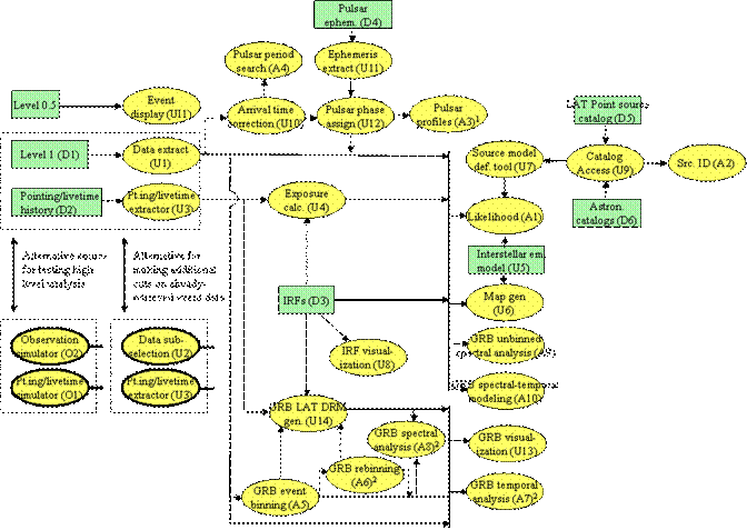
Figure 2.9
For the purposes of subsetting already-extracted event data, without generating a query for the database, the SAE includes U8 to interactively apply additional cuts to the locally-stored Level 1 data. This is also depicted as an alternative data source for the high-level analysis.
2.10User interface
The user interface components of the SAE relate to the interactions between users and analysis tools in general, such as common scripting or graphical user interfaces, or for specific applications, such as the event display UI1 discussed above. The general user interface components are not explicitly included in the dataflow diagrams described in the preceding sections. They are listed and briefly described in Table 2.5.
2.11Summary of the standard analysis environment
The final diagram of the SAE (Fig. 2.10) has data flow generally progressing from left to right, from lowest-level to highest-level data products. The components of the analysis environment shown in the diagram are also listed in Tables 2.1-2.5 [which may introduce data formats and include links to their relevant tools.]
Fig. 2.10 The overall data flow in the standard analysis environment.
In most cases, the software and database components of the SAE will be installed on client computers. The principal exception is the Level 1 database (D1), which we anticipate will run on specialized, dedicated central servers in order to provide adequate data retrieval capability. The instrument response functions (D3), depending on the ultimate size of their implementation in CALDB, might also be made available for remote access from servers at LAT sites and the SSC.
|
ID |
Name |
Description |
Size after 1 year |
|
D1 |
Event Summary (level 1) |
Summary information (i.e., everything needed for post-Level 1 analyses) for photons and cosmic rays, possibly segregated by event classification |
200 Gb (only 10% photons) |
|
D2 |
Pointing, livetime, and mode history |
Timeline of location, orientation, mode, and accumulated livetime |
70 Mb |
|
D3 |
Instrument response functions |
PSF, effective area, and energy redistribution functions in CALDB format |
TBD |
|
D4 |
Pulsar ephemerides |
Timing information (maintained during the mission) for a set of radio pulsars identified as potential LAT sources |
1 Mb |
|
D5 |
LAT Point source catalog |
Summary information for LAT-detected point sources, from which the LAT point source catalog is extracted |
10 Mb |
|
D6 |
Other high-level databases |
Astronomical catalogs useful for counterpart searches for LAT sources |
TBD |
Table 2.1 Databases
|
ID |
Name |
Description |
|
U1 |
Event data extractor |
Basic front end to the event summary database D1 |
|
U2 |
User-level data extraction environment |
Allows the user to make further cuts on the photons extracted from D1, including energy-dependent cuts on angular distance from a pulsar position |
|
U3 |
Pointing/livetime history extractor |
Basic front end to the pointing, livetime, and mode history database D2 |
|
U4 |
Exposure calculator |
Uses IRFs (D3) and pointing, livetime and mode history (D2) to calculate the exposure quantities for the likelihood analysis (A1) |
|
U5 |
Interstellar emission model |
Not software per se, although the model itself will likely have parameters (or more complicated adjustments) that need to be optimized once and for all, in concert with an all sky analysis for point sources. |
|
U6 |
Map generator |
Binning of photons, regridding of exposure, coordinate reprojection, calculation of intensity |
|
U7 |
Source model definition |
Interactive construction of a model for the region of the sky by specifying components such as the interstellar emission, point sources, and extended sources, along with their parameter values; the resulting models can be used in the likelihood analysis (A1) and the observation simulator (O2) |
|
U8 |
IRF visualization |
Extracting PSF, effective areas, and energy distributions from the CALDB (D3) for visualization |
|
U9 |
Catalog access |
Extracting sources from catalogs, LAT and otherwise (D5 & D6) |
|
U10 |
Gamma-ray arrival time barycenter correction |
For pulsar analysis |
|
U11 |
Pulsar ephemeris extractor |
Interface to the pulsar ephemeris database (D4) |
|
U12 |
Pulsar phase assignment |
Using ephemeris information from U11 and barycenter time corrected gamma rays from U10, assigns phases to gamma rays |
|
U13 |
GRB visualization |
Displays various types of GRB lightcurves and spectra |
|
U14 |
LAT GRB DRM generator |
Generates the detector response matrix appropriate for fitting binned LAT GRB spectral data. |
Table 2.2 Utilities
|
ID |
Name |
Description |
|
A1 |
Likelihood analysis |
Point source detection, characterization (position, flux, spectrum), generalized models for multiple/extended sources |
|
A2 |
Source identification |
Quantitative evaluation of the probability of association of LAT sources with counterparts in other catalogs |
|
A3 |
Pulsar profiles |
Phase folding of gamma-ray arrival times (after phases are assigned by A3) and periodicity tests |
|
A4 |
Pulsar period search |
Search for periodic emission from a point source |
|
A5 |
GRB event binning |
Bins events into time and energy bins |
|
A6 |
GRB rebinning |
Rebins binned GRB data into larger time and energy bins |
|
A7 |
GRB temporal analysis |
Analyzes GRB lightcurves using various techniques such as FFTs, wavelets, etc. |
|
A8 |
GRB binned spectral analysis |
Fits binned spectra; may be XSPEC |
|
A9 |
GRB unbinned spectral analysis |
Fits event data with spectral models |
|
A10 |
GRB spectral-temporal physical modelling |
Fits a GRB physical model to LAT or LAT+GBM data |
Table 2.3 Analysis tools
|
ID |
Name |
Description |
|
O1 |
Livetime/pointing simulator |
Generates simulated pointing, livetime, and mode histories (analogue of D2) for a specified time range and observing strategy. This should be available as a tool, but probably most generally useful will be precomputed simulated D2 databases, which can be used subsequently for any study with O2. |
|
O2 |
High-level observation simulator |
Generates gamma rays according to the instrument response functions (i.e., after detection, reconstruction, and background rejection), bypassing the instrument simulation step |
Table 2.4 Observation simulation tools
|
ID |
Name |
Description |
|
UI1 |
Event display |
Displays the tracks of an individual event, requires access to Level 0.5 data |
|
UI2 |
Image/Plot display |
General facility for image and plot display |
|
UI3 |
User Support |
Defines the scope of user support at the level of the components of the standard analysis environment |
|
UI4 |
Command-line interface and scripting |
Requirements for command line and scripting interfaces to the components of the standard analysis environment |
|
UI5 |
GUI interface and Web access |
GUI interface to the standard analysis environment. For some tools, especially U1 and U4, which have databases stored on a remote server, Web access seems most practical. |
Table 2.5 User interface
3 User environment
3.1 User interface
The suite of analysis tools and utilities constitute the standard analysis environment that will enable users to analyze the LAT data. The users will access these tools through two different interfaces according to their temperament, experience and needs. The first is a command line interface that will be familiar to UNIX users and to X-ray astrophysicists experienced in running FTOOLS. In the second the tools will be run through an overarching GUI-based environment, and the tools will interact with the user through GUIs. Through the use of I/O libraries both interfaces can be implemented. From the viewpoint of the software development, the command-level interface may be more fundamental since the GUI-based interface binds together the tools that are separate entities in the command-line interface, but from the viewpoint of most users, the GUI-based interface may predominate. Of course, some users may mix the two interfaces, using the GUI-based interface to prepare the data for a particular analysis, and then running a particular tool, or group of tools, with user-defined scripts that perform or automate the analysis (e.g., fitting series of spectra in a particular way).
3.1.1 The command line interface
The tools can be divided into two categories. Some tools will perform single, specific tasks, and after they are entered, they will require very little, if any, further input from the user. Following Unix tradition, some information may be passed as optional arguments, or as with HEASARC's FTOOLS or the Chandra data analysis system's CIAO tools, there may be "parameter files" containing default values for various options that can be readily modified by the user. Examples of LAT command line tools include the pulsar phase assignment program (U12) and the LAT GRB response matrix generator (U14). Several existing generic HEASARC FTOOLS, such as fselect and fcopy, will also be useful for manipulating LAT data.
Several of the LAT analysis tools will require a substantial amount of interactive input from the user. The primary example is the likelihood analysis tool (A1) that will require the user to adjust the gamma-ray sky model by adding sources, changing source positions, freezing and/or thawing model parameters, etc., in order to facilitate the fitting process. Other examples of interactive programs include the source model definition Tool (U7) and the GRB spectral modeling tools (A8-A10).
A strength of the command line interface is that users can easily create new tools through scripting. The scripts may be embedded in the tool; a possible prototype is the HEASARC's X-ray spectral analysis program XSPEC. Programs such as the likelihood tool (A1) will have a command-line interface, and a scripting language could be embedded in a fashion similar to the use of Tcl (Tool Command Language) in XSPEC. Alternatively, the tools may be linked together with scripts. The integration of the IRAF command language as an extension of the increasingly popular Python scripting language may serve as a model. In this approach, the scripting language interpreter provides the analysis environment; and functions for manipulating and analyzing the LAT data are added by implementing them as loadable extension modules.
In either case, we reap the benefits of adding scripting: the scripting language adds a "macro" capability. Repetitive tasks, such as fitting a number of different datasets with the same source model, can be readily automated using the control structures of the scripting language. Complex sequences of analysis tasks can be put into a single script. This will enable users to keep track of their analysis sequences, and their scripts will augment the functionality the likelihood tool (A1), while still allowing the set of basic tasks to be well-defined and relatively small in number. In addition, the scripted routines can be readily modified to suit the individual needs of each user. Another benefit of having a scripting capability is that it greatly facilitates the implementation of a graphical interface to our tools. Scripting languages such as Tcl, Perl, or Python have programming support for the popular Tk widget libraries as well as other graphical interfaces, and these languages provide more efficient GUI programming than do the corresponding C++ APIs.
3.1.2 The GUI-based interface
In the GUI-based interface the user will invoke the tools through GUIs and then will interact with the tools through the GUIs. Since the GUIs present the user with standard analysis options, this interface will make it particularly easy for new and occasional users to analyze LAT data. We will endeavor to make most types of analysis possible through the GUI interface, but in some cases an advanced user will require the added control afforded by the command-line interface and the scripting capability.
The GUIs will be designed to give the interface a unified look and feel. The same terminology will be used throughout, and standard buttons (e.g., for help or exiting a tool) will be in the same place. Pop-up windows to input or output files will start in logical default directories, and GUIs to modify parameter values will present the current sent of parameters as the default.
The BATSE GRB analysis tools RMFIT (developed at MSFC) and SOAR (developed at UCSD) are two examples of the integration of different analysis functionalities into a single environment with the use of GUIs and graphics. In particular, RMFIT implements interactive graphics. Unfortunately, both of these burst analysis tools are written in IDL, a commercial data analysis environment, and therefore cannot be distributed as official tools
3.2 Distribution plans
3.2.1 Data Distribution Plans
The LAT IOC will transfer post-Level 0 data to the SSC, and to one or more mirror sites for use by LAT team members in other countries. (The MOC will deliver the Level 0 data directly to the SSC for archiving, as described in the report of the Data Products Working Group. The data available at the SSC will also be mirrored at the ASI Science Data Center.) Of primary interest for the SAE are the data required for the databases listed in Table 2.1. These data sets will most likely be transferred from the LIOC to the SSC using the Data Transfer System (DTS), a set of Perl scripts written for transferring data between centers for the XMM mission; Swift will also use DTS. During Phase 1 access to the Level 1 data is restricted to the LAT team for validation and verification and to a small number of guest investigators. Level 1 data for transients (GRBs, bright blazar flares, and solar flares) will be supplied to the SSC as soon as the Level 1 processing is complete for immediate release.
Once the Level 1 data become publicly available in Phase 2, investigators from the general scientific community will extract data from the SSC’s databases. The data extraction utilities U1 and U3 (see §2) will be run on the SSC’s servers through the SSC’s website. The extracted data will be formatted into FITS files that the investigators will transfer (e.g., by ftp) back to their home institutions. In a limited number of cases where network distribution is impractical, the SSC will distribute it by CD-ROM or DVD. To obtain LAT data from the SSC a scientist must become a “qualified investigator” by identifying him/herself to the SSC as a legitimate investigator. Respecting the GLAST mission’s data policies, the ASDC will supply data to Italian astrophysicists. Note that in Phase 2 there are no proprietary data, only a 90 day proprietary period for specific investigations after all the necessary data become available for the research proposed by a successful guest investigator.
3.2.2 Software Distribution Plans
Some of the data extraction tools will be run on the database servers, however most of the science analysis tools will be downloaded to the investigator’s computer. As discussed below, we currently plan to support the Windows and Linux operating system; other flavors of Unix will be considered based on their popularity in the astrophysics community. As far as possible, we will adhere to portable coding practices, including the isolation of system-dependencies. The LAT science tools will be distributed over the internet as compressed tars files or RPMs for Linux users and as zip files for Windows users. The general scientific community will download these files through the SSC’s website. The distributed files will contain executable binaries for all the software, a README file, release notes, source code, and documentation covering the installation and usage of the software. Note that both the executable binaries and the source code will be provided, as is the standard practice for high energy astrophysics missions. Further documentation on the LAT science tools will be posted on the SSC website. Only in rare cases will the GLAST science analysis software be available on other media—CD-ROM, DVD, or tape—and distribution by this method will be considered only on a case by case basis.
3.3 Documentation and help
User Guides and Reference Manuals for all of the LAT analysis software will be available on-line, both as standard web pages and as appropriately formatted down-loadable PDF files. These documents will describe the use of the analysis tools as well as the algorithms underlying them and the circumstances that are appropriate for applying each tool. Following the example of CIAO, we will have web pages of "analysis threads". These are essentially detailed use cases that show the precise sequence of commands, along with appropriate explanations, to do a particular analysis. We will also maintain a web archive of useful analysis scripts that have been produced internally or submitted by users. It is expected that the content of the analysis threads web page and script archive will evolve and grow as the mission matures. Guidelines for preparing the scripts will be provided, and user-submitted scripts will be vetted and tested before being made part of the archive.
For the command-line tools as well as for commands executed from within the interactive tools, standard reference manual documentation will be provided in a format similar to Unix man pages. The content of the man pages will be accessible from a searchable web page that has hypertext links for all supported concepts. This will be similar to the web-based ahelp documentation provided by CIAO.
Finally, we will have a "help-desk" service to which users can make inquiries regarding LAT data analysis, the software itself, or bug reports. Submissions can be made either to the help-desk email address or through a web interface. In order to facilitate interaction between the users and the help-desk service, specific guidelines for reporting bugs will be provided. All inquiries and responses will be logged; and as user questions or bug-reports accumulate, we will archive the more common inquiries and their resolutions on a FA web page.
4 Use cases
4.1 Determine the Average Spectrum of 3C 273 For a Particular One-Month Period
1. Extract the gamma-ray data from the event summary database (D1) for this period of time for a region of sky centered on 3C 273. The minimum size of the region is dependent on the minimum energy desired for the spectral analysis; U1 will provide guidance. (The rule of thumb is that the region of the sky has to be large enough so that the analysis of 3C 273 is not affected by point sources that are outside the region selected.) At this stage, additional cuts on the gamma rays can be imposed, such as on zenith angle or inclination angle. Again, U1 will provide guidance about standard cuts. Specification of the class(es) of gamma rays may also be made at this time. The classes are presently TBD; for example, distinct classes of gamma rays with good energy measurement or direction determination might be defined.
2. Calculate the corresponding exposure using U4. U4 can automatically generate the exposure matrices with the same cuts as used for a gamma-ray dataset produced by U1.
3. Next, define a model for the gamma-ray emission in the region of the sky using the source model definition tool U7. This should be largely automatic, at least for models containing only the interstellar emission, an isotropic component, and point sources. U7 understands the parameters of the interstellar emission model (U5) and will have access to the current catalog of LAT point sources (D5), perhaps even for the particular time range of interest. The catalog will include position, flux, and (most likely) spectral index estimates for point sources in the region of the sky. The output of U7 is the definition of the model (interstellar emission terms, isotropic emission spectrum, and point source positions, fluxes, and spectral indices) readable by the likelihood analysis tool A1.
4. At this point, it would be a good idea to visually inspect the data for the region to be analyzed by generating maps of intensity both for the observations (via U6) and for the model (an optional output of U7). The maps can be displayed using the display utility U2.
5. Then use the likelihood analysis tool A1 to first optimize the positions and fluxes assumed for the point sources, and any adjustable parameters for the diffuse emission model, in the region analyzed using the source model and the gamma-ray and exposure data. (The positions of identified sources should be constrained to remain fixed at their catalog values during this optimization.)
6. Have A1 write an updated model definition, then use this model definition in A1 to search the region of interest for additional point sources that might have missed inclusion in the general catalog. The source identification tool (A2) may be used at this time to determine if counterparts for these sources have been seen at other wavelengths. It may also be desirable at this point to remove any point sources that are not actually detected in this time range. In support of the analysis, A1 can display likelihood test statistic maps, the model intensity, the (observed minus modelled) excess map, and the locations of point sources in the model, using the display utility U2. After a final optimization pass for the source parameters is performed, have A1 write the final model for the point sources.
7. Two approaches for deriving the spectrum of 3C 273 are possible at this point. The first approach is to modify the model to use different spectral models for 3C 273 (e.g., a power-law with a spectral break), and reoptimize the parameters to see which spectral model best represents the data. In this case, the results are represented by the values of spectral parameters adopted for the model of 3C 273. The second is to re-run A1 using the final model and narrower energy ranges (~factor of 2 wide, collectively spanning the energy range of interest), to derive fluxes and confidence intervals. This process can be automated using the scripting capability of A1, and template scripts should be available. The result should be a flux measurement (or upper limit) for each energy range and a corresponding plot.
4.2 Determine the Light Curve of 3C 273 For a Particular One-Month Period
Steps 1–5 for this analysis are the same as for the spectral analysis described above. After these steps, the model for the diffuse emission and the point sources in the field should be established. Note that for short time intervals, such as will be analyzed here, the spectral model for 3C 273 need not be particularly complex. A power-law will suffice, and it may even be worth evaluating whether holding the spectral shape fixed at some representative form increases the flux sensitivity enough (by reducing the number of degrees of freedom in the likelihood function) that fluxes can be measured on shorter time intervals.
6. Based on the detection significance of 3C 273 in the whole month interval, decide what time interval will be used for evaluating the flux. Most likely this will be days.
7. Extract gamma-ray data sets (U1 to query D1 or U8 to subset a previously-extracted set of gamma-ray events), generate corresponding exposures (U4) for each of these intervals, and reoptimize the model parameters for each time interval (A1) to determine the flux and confidence interval (or upper limit). U8 can be used to subselect already-extracted data by time range (The fluxes and positions of the other point sources in the region probably can be held fixed for this analysis.) This can be done for various energy ranges subselected from the gamma-ray and exposure datasets if desired. Note that this process of extracting data, generating exposure, and applying a common model in the likelihood analysis, can be automated.
8. If desired, time intervals can be lengthened or shortened based on the findings in step 7, and the analysis re-run.
4.3 Study Gamma-Ray Emission From a Pulsar
Study of pulsars with LAT data can follow two paths. The first is evaluation whether periodic emission is evident in the data and the second is characterization of the pulsar as a point source using phase selected data in the likelihood analysis tool A1. Both approaches start with extracting gamma-ray data from the vicinity of the pulsar, using U1 as in use case #1:
1. Extract the gamma-ray data (U1) for a region of the sky around the pulsar large enough for point-source analysis, for the time and energy ranges of interest.
2. Extract pulsar ephemeris (U11) for the pulsar, if it is known in D4, by specifying the name of the pulsar or a region of the sky, and the time of observation.
3. Calculate barycentric photon arrival times (U10) by specifying a provisional or known pulsar position.
4. To enhance the detectability of periodicity in the LAT data, the gamma-ray data may need to be passed through U2, which selects the gamma rays within a certain (energy and inclination angle dependent) radius of the position of the pulsar. This cut discriminates against the diffuse gamma-ray emission. The position of the pulsar may be specified either via a pulsar ephemeris extracted from D4 in step 2 or explicitly.
Periodicity searches and periodicity significance tests:
5. If the pulse frequency at the time of observation is completely unknown, search for pulsations in the gamma-ray data in a wide range of timing parameters (A4). A4 will generate a plot of significance of periodicity in the data as a function of trial frequencies and frequency derivatives. Once a pulsation is found, periodicity tests can be applied at pulse frequencies close to the one determined in this step (A3), in a manner described in the next step.
6. If the pulse frequency at the time of observation is approximately known, search for a pulsation in the gamma-ray data at pulse frequencies close to the expected one (A3) by specifying either a pulsar ephemeris extracted from D4 in step 2 or the timing parameters explicitly, with a range of the search. A3 will apply periodicity tests to the data and generate a plot of significance of periodicity in the data as a function of trial frequencies.
Phase-binned analysis:
7. Assign phases to these gamma-rays (U12) by specifying either a pulsar ephemeris extracted from D4 in step 2, the timing parameters determined by step 5 or 6, or the timing parameters explicitly.
8. Use U4 to calculate the exposure corresponding to the gamma rays extracted by U1. U4 can automatically generate the exposure matrices with the same cuts as used for a dataset produced by U1.
9. The rest of the analysis proceeds as in steps 3-6 of use case #1, with the exception that A1 can be told what phase range to include. For the likelihood analysis, it selects only the gamma rays in the specified phase range and scales the exposure by the fraction of the phase range selected. In this way, phase resolved fluxes, spectra, and even source position maps can be derived. The scriptability of A1 will allow this process to be automated once the desired phase ranges are found. In particular, an initial analysis of all of the data could be used to fix the parameters of the interstellar emission model and of the other point sources in the region, and then the automated analysis could be scripted to use these values while optimizing the pulsar flux and spectrum for each phase range.
4.4 Binned GRB Spectral Analysis
1. The GBM and LAT teams localize the burst. Notices have been sent out by GCN.
2. LAT data are extracted for a region with a radius of ~1 PSF at the lowest energies (U1 applied to D1; further cuts may be applied by U2). Special cuts may be applied to increase the number of photons at the expense of increasing the PSF.
3. The pointing history for the time of the burst is extracted for the time of the burst (U3 applied to D2). The time sampling may need to be increased relative to the default, at the very least for an accurate deadtime estimate. For short bursts a single pointing direction may suffice.
4.GBM burst data is extracted (or provided by the GBM team). Event data will be available from just before the trigger for a certain time after the trigger. Additional binned background data will also be available.
5. Event data from other missions (e.g., Swift, Integral) may also be available. These data will be accompanied by the appropriate detector response matrices (DRMs). DRMs relate the incoming burst spectrum to the observed event spectrum. The events are often called “counts.”
6. The light curves at different energies can be studied using the visualization tool (U13). This will give the analyst a feel for the structure of the burst, its duration, and its spectral evolution. If the analyst chooses to use his/her own time binning for the spectroscopy, this is where he/she will choose the time bins.
7. The event data for the different detectors are read into the GRB Event Binning tool (A5). The analyst will input the desired energy bins. He/she will choose among a number of time binning schemes. Currently planned are: user input; constant time width; signal-to-noise ratio (S/N) bins; and Bayesian Blocks. For the S/N and Bayesian Blocks binning the analyst will input the desired detector data and energy range that should be used; these methods may have other parameters. The binning tool (A5) will then bin the event data into energy and temporal bins. The output will be PHA2 files readable by XPSEC. The XSPEC family of files does not include the livetime or energy bins in the PHA files, but puts this information in the ARF and RMF files used for the DRMs. A5 outputs an ARF file with the livetime equal to the width of the time bin and unit effective area, and an RMF file with the energy channels defined and a perfect energy redistribution matrix.
8. Where relevant, A5 will also produce background files (in PHA2 format) using background models generated elsewhere. Few if any background LAT photons are expected in the region around the burst during the burst’s short duration; with an expected photon rate of a few Hz spread over a large FOV, very few non-burst photons will fall within the extraction region (which will be only ~0.03 sr). Therefore no background calculation is necessary for LAT data.
9. DRM generating tools are called for the different detectors. For the LAT this tool is U14. U14 integrates the LAT’s IRF over the region the LAT photons are accumulated; this integration accounts for the photons that fall outside this region. The DRM generating tools take in the incomplete ARF and RMF files produced by A5, and add the effective area to the ARF file and the energy redistribution matrix to the RMF file. In addition, U14 will apply a livetime fraction to the width of the time bins in the ARF file. A5 will produce a series of spectra. If the spectra have different width time bins, an ARF file is necessary for each spectrum. Different RMF files are necessary only if the angle between the burst and the LAT normal changes significantly during the burst.
10. If the GBM data are already binned, they can be rebinned in time using A6 to accommodate the temporal binning of the other data. Note that the non-burst background is necessary for GBM data; the relevant tool will be developed outside of the LAT science tool effort.
11. The result of the above steps is the necessary input to XSPEC, which we plan to use as A8. Standard burst spectral models, such as the “GRB” model, are in XSPEC’s library. XSPEC can perform joint fits to different data sets. While XSPEC can read in PHA2 files that contain more than one spectrum per file, fitting series of spectra requires a script run within XSPEC.
12. The resulting fits can be compared to the data using the visualization tool (U13). A8 outputs a file with the spectral fits that U13 will use to compare the data and the model.
4.5 Binned GRB Temporal Analysis
Apply steps 1-10 of Case 4.4 to get the burst data from the different datasets binned temporally. For most analysis methods constant time width bins should be used. The desired energy bins can be used ab initio, or the temporal analysis tool can sum the energy bins as needed.
11. Input the PHA2 files with the binned data into the temporal analysis tool (A7).
12. Choose the desired options in A7. For methods such as FFT, wavelet and pulse decomposition, a single time series needs to be identified (detector and energy band). For cross-correlations two time series need to be identified.
4.6 Unbinned Burst Spectral Analysis
Apply steps 1-3 of Case 4.4 to extract photons from a region around the burst for a time period of interest, and to extract the pointing history for this period. One spectrum at a time is fit in this method; thus the burst data are binned in time and unbinned in apparent energy.
4. Use U14 to calculate the “exposure” for the burst photons. The precise form of this exposure will depend on the formulation of the likelihood.
5. Use A9 to perform the unbinned spectral analysis. A9 uses the likelihood for the detected LAT photons; standard spectral models (e.g., power law, “GRB”) are built into A9.
6. The results can be visualized using U13.
4.7 Make a Sky Map Image
1. Extract the gamma-ray data for the desired time range, energy range, region of the sky, event type, etc. using U1.
2. Generate the corresponding exposure using U4 as in use case 1 above.
3. Use the map generator (U6) to bin and grid the gamma rays in the desired projection, either for the energy range and region of the sky, etc. of the initial selection (step 1) or for sub-selections of these ranges. In general, some parameters (like inclination and azimuth) will be integrated over (or 'marginalized') in this step. Intensity maps for energy ranges broader than the energy resolution will be constructed as the sum of intensity maps for narrower ranges, so that spectral variations will not skew the weighting of the energy ranges with respect to each other.
4. Do the same with the exposure using U6. In this case, no binning is required, of course. (The exposure is tabulated or perhaps parameterized.) However, the same marginalizations that were applied to the gamma-ray counts must also be applied in this step. Also, a gamma-ray spectrum must be assumed at this step, so that the energy dependence of the effective area is properly weighted. It is likely that a standard value for the assumed spectral index (like -2.1, which was used for EGRET) is sufficient. It is probably not worth the trouble to try to derive the spectrum (which in any case would depend on position) from the gamma-ray and exposure data themselves.
5. Display the resulting counts, exposure, and intensity (counts/exposure) maps using the image display tool U2. It is assumed here that U2 understands how to make map projections and can also adjust, e.g., the color table.
6. U2 and the catalog access tool U9 can be used to plot overlays of sources extracted from astronomical catalogs if desired.
4.8 Multimission Point Source Analysis
Perform steps 1-5 of the standard point source analysis (i.e., as in use case 1) to derive a model for the region surrounding the point source of interest.
6. For the point source of interest extract count spectra, background spectra and IRFs from the non-LAT detectors. Read this data into the likelihood tool, linking this data to the spectral parameters for the point source of interest. If needed, define intercalibration parameters to accommodate the errors in the normalizations of the different detectors.
7. Perform a joint fit between the LAT and other detectors’ data. In general, the parameters corresponding to the surrounding region will be held fixed while the parameters describing the source will be fit.
8. The fit to the count spectra from the other detectors can be displayed. Various goodness-of-fit measures can be inspected.
4.9 Observation Simlations for Evaluating Prospective Observations
For proposals of pointed observations as well as for assessing the feasibility of coordinated multiwavelength campaigns, the LAT observation simulation software can be used.
1. Determine the time range for the proposed observations, based on constraints such as telescope availability, source visibility, etc.
2. Run the livetime/pointing simulator O1 for the desired time range. One will generally use standard orbit parameters as input, but it will probably be desirable to consider different observation types (survey mode, pointed, or pointed scan) and observing strategies.
3. Use the source model definition tool (U7) to specify the point sources and interstellar emission model to be used. One may wish to map out the likely parameter space of the sources by varying their spectral and temporal properties, thereby creating several different models to test.
4. The livetime/pointing output of O1 and the source model(s) of U7 are then fed to the high-level observation simulator O2. O2 creates photon event lists that are identical in format to the output of the photon database extractor U1.
5. The output of O1 and O2 can then be analyzed as in the previous use cases to determine what sort of constraints can be placed on the sources given the prospective observations.
5 Development concept
5.1 Management
We recognize several challenges to the development of the SAE: widely-dispersed contributors who represent a broad range of experience in astronomy and software development and work for different institutions. We also recognize that scope of the development effort is broad, and development needs to proceed in parallel on several fronts. Some of the components that are vital to the SAE, including the Level 1 database system and the core Likelihood Analysis tool, have stringent performance requirements and owing to the nature of the LAT and the its scanning observing mode, will not directly inherit from existing analysis systems. Below the management approaches that are being implemented to mitigate each of these challenges are described.
We are already taking advantage of Internet-based tools, such as the VRVS conferencing system and instant messaging software, to keep in regular contact across the science tools definition effort. Weekly meetings to discuss issues related to the definition of the analysis environment are already taking place (http://www-glast.slac.stanford.edu/ScienceTools/meetings) and these will transition to meetings about development progress and issues. The SSC-LAT Working Group also meets weekly via VRVS (http://www-glast.slac.stanford.edu/ScienceTools/slwg/meetings). Also, although the developers of the SAE will be widely distributed geographically, the code management will be via a central cvs repository at SLAC. This has been implemented and used successfully for the development of GLEAM, the LAT instrument simulation tool. The central repository facilitates code versioning, code sharing, and routine build testing.
Regarding the organization of the such a broad development effort, the tools and databases may be grouped fairly naturally by function into a few areas: databases and related utilities for accessing them, analysis tools, observation simulation, and user interface. Analysis tools further divide into source detection, source identification, pulsar studies, and GRB studies. Rather than having one person (or the SSC-LAT Working Group members collectively) attempt to oversee development of all of the components and the interfaces between them, the development effort within each of the 7 areas (Table 5.1) will have an assigned manager. The managers will be named by the SSC-LAT working group for their experience in the corresponding subject and their willingness to devote the required time to the oversight work. These managers will be responsible for monitoring implementation plans (development of prototypes), progress with respect to the schedule, component-level testing (see §6.1), and the interfaces with the other development areas. This will permit close oversight of the development effort and clearly-defined communications between development areas. The managers will report to the SSC-LAT working group, and completed modules will be delivered to the working group. The latter will oversee functional testing, code reviews, and documentation reviews before acceptance. (Note that testing and reviews like these are planned throughout the development process; see §6. The SSC-LAT working group will oversee acceptance testing and review.) Releases of the analysis environment will be coordinated with the planned Mock Data Challenges (described in §6.3).
|
ID |
Component |
|
|
Databases and related utilities |
|
D1 |
Event summary (gamma rays and all events) |
|
U1 |
Event data extractor |
|
U2 |
Subselections on already-extracted event data |
|
D2 |
Pointing/livetime/mode history |
|
U3 |
Pointing/livetime/mode extractor |
|
D6 |
Other high-level (incl. GRB, transient summaries, astron. catalogs) |
|
U9 |
Catalog access tool |
|
|
Source detection (likelihood analysis) |
|
D3 |
CALDB for IRFs |
|
U4 |
Exposure calculator |
|
U7 |
Source model definition |
|
U8 |
Response function visualization (for D3) |
|
A1 |
Likelihood analysis |
|
|
Pulsars |
|
D4 |
Pulsar ephemerides |
|
U10 |
Barycenter arrival time corrector |
|
U11 |
Pulsar ephemeris extractor |
|
U12 |
Phase assignment |
|
A3 |
Pulsar profiles, periodicity tests |
|
A4 |
Period search |
|
|
GRBs |
|
U13 |
GRB visualization |
|
A5 |
GRB event binning |
|
A6 |
GRB data rebinning |
|
A7 |
GRB temporal analysis |
|
U14 |
LAT GRB DRM generator |
|
A8 |
GRB binned spectral analysis |
|
A9 |
GRB unbinned spectral analysis |
|
A10 |
GRB spectral-temporal physical modeling |
|
|
Catalog analysis |
|
D5 |
LAT point source catalog |
|
U5 |
Interstellar emission model |
|
U6 |
Map generator |
|
U9 |
Catalog access (for D5) |
|
A2 |
Source identification |
|
|
Observation simulation |
|
O1 |
Livetime/pointing simulator |
|
O2 |
High-level observation simulator (which will contain modules for the various source classes) |
|
|
User interface |
|
UI1 |
Event display |
|
UI2 |
Image/plot display |
|
UI3 |
User support |
|
UI4 |
Command line interface and scripting |
|
UI5 |
GUI interface & Web access |
Table 5.1 The 7 development areas for the SAE. The associated tools and databases are indicated.
At the module level, development responsibility will be assigned by the SSC-LAT working group, again based on interest and experience. The working group reserves the right to replace managers and tool developers (in consultation with the managers) in the event that development or management effort doesn’t meet expectations. Ultimate responsibility for the analysis environment lies with the instrument team, and in the unexpected circumstance that the overall organization of the development effort is found to be deficient, fundamental changes will be made as required.
For the LAT-specific core components of the SAE, we have endeavored to identify the open issues, i.e., options for implementation, that need to be evaluated. The schedule and resource assignments (§7) have been constructed to allow time for the development decisions to be made rationally, and with fairly conservative completion dates (tied to the Mock Data Challenges) that allow time if needed for late changes of direction or other implementation challenges with the core components.
5.2 Languages
The main language we will use for implementation of the science tools is C++, making use of the object oriented design capability and superior performance (as compared with e.g., Java). If the need arises, contributions to the code for specific algorithms can be accepted in other languages (e.g. FORTRAN) provided robust compilers are available for that language for the operating systems we will support, and the resulting compiled code can be wrapped into C++ classes.
We will be using coding standards developed by the LAT team developing the low-level simulation of the LAT and the track reconstruction code
(http://www-glast.slac.stanford.edu/software/CodeHowTo/codeStandards.html). Standards for in-line code documentation have also been adopted from LAT procedures (http://wwwglast.slac.stanford.edu/software/core/documentation/doc/codeRecommendations.pdf).
We are planning to provide a scripting capability to users. The goal is to provide the user with the ability to: 1) easily build scripts to perform sets of analyses, and 2) to provide an easy interface to customize the analysis. The idea is to contain the core functionality of the analysis tools in shareable C++ libraries. We will then build wrappers for the C++ libraries as modules in the appropriate scripting language. The scripting language of choice has not been finalized, but contenders are perl, python, and ruby. Note that open source tools exist (like SWIG http://www.swig.org/) which can easily build such wrappers in all three scripting languages from C++ source code.
Operating systems we intend to support are Windows and Linux.
5.3 Development Environment
Development will take place on both Windows and Linux platforms, so some of the development tools will be platform specific, and some will work on both platforms.
The common tools for version tracking (CVS - http://www.cvshome.org), for configuring software builds (CMT - http://www.cmtsite.org), and for code documentation (doxygen - http://www.stack.nl/~dimitri/doxygen) are good, stable, and have been successfully used by the LAT team for years now. CVS is a version tracking program that allows remote access to the code repository. The same repository will be used for both Unix and Windows code, as is done currently by the LAT team. CMT allows all aspects of the build configuration to be controlled for any given package with a single “requirements“ file. CMT uses this to automatically generate makefiles and executes them to build the binaries. The doxygen tool generates documentation in HTML and Latex, so it can be either posted for web searching (most commonly used mode) or compiled into a postscript document for printing. The documentation is inserted in specially formatted comments in the code.
The code writing/debugging environment is different for the two platforms (unix and Windows, Table 5.1)
|
Tool |
Linux |
Windows |
|
C++ compiler |
gcc |
VisualC++ |
|
C++ debugger |
ddd/gdb |
VisualC++ |
|
Java compiler |
javac |
VisualJ++ |
|
Java debugger |
jdb /jde/xemacs |
VisualJ++ |
Table 5.2 Compilers and debuggers for the supported operating systems
The Java tools are included to cover the possibility that the graphical interface will be done with Java.
The intention is make the tools compatible with the HEASARC FTOOLS. At this point it is not clear whether this means adopting the whole HEAdas package or using part of HEASARC software, such as CCFITS for reading FITS files in C++.
The handling of bug reports from users is described in UI3 in Appendix C. The SSC-LAT working group will oversee tracking of bug fixes. During development of the SAE a bug reporting e-mail distribution list will be implemented and bug tracking software, e.g. Bugzilla (http://www.bugzilla.org) will be investigated.
5.4 Code Package Development and Hierarchy
The CMT code management tool (http://www.cmtsite.org/), which we will use for the SAE, encourages the development of modular code into ‘packages.’ Each package could contain a high-level analysis tool or utility (the A and U components of the 'SAE), or a base utility used by more than one tool. In addition CMT incorporates the concept of bundling constituent packages into applications. An application can be either an executable that loads various tools into memory as needed, or a standalone executable for a single tool. The required versions of the constituent packages that are needed for a tool can be specified in CMT. The use of well-defined class libraries and shareables allows construction of well-separated code units (avoiding “spaghetti code”) with a hierarchy spanning basic utilities at the bottom to the analysis tools set at the top. This encourages re-use of code through the common basic utilities.
A code infrastructure (sometimes referred to as an archictecture, see http://proj-gaudi.web.cern.ch/proj-gaudi/GDG/v2/Output/GDG_Architecture.html#1010951) will be defined for the SAE. It will enforce uniform coding practices and define the general layout of the code itself. The important common functions among the analysis tools (e.g., for i/o or manipulations of times or coordinates) will be defined by base classes and interfaces used by the packages’ algorithms.
Our planned use of C++ standard library components, which are widely supported across compilers, allows common functionality across platforms.
6 Testing methodology
We plan to base much of the testing methodology on the already existing LAT ground software test plan, described in LAT-TD-00875. This plan describes the testing elements that will be used to ensure the quality of the software throughout the development and integration of software elements of the SAE:
· Package standalone tests: These consist of test programs with scope restricted to just that functionality of the package being tested. A package can have many unit tests (i.e., tests of individual components of the package), but must have at least one that can be run by the test server that demonstrates fulfillment of the requirements for the package.
· Application system tests: Suites of tests applied at the analysis tool level. For example, these could be the individual elements used in a particular analysis chain, such as data extractor, exposure calculation, model definition, likelihood analysis, and the user interface display tool. These tests can include information specific to constituent packages and be dependent on the interaction of packages with each other as well as on the overall performance of the tools.
· Nightly package builds: Attempts to build and run a unit test for the package HEADs (development version of the code in the CVS repository) each night. Packages that lack unit tests will be flagged.
· Code reviews: Periodic reviews of code at the package level, examining adherence to coding and documentation rules, with an eye to visual inspection of algorithms.
· Performance reviews at the analysis tools level
The Release Manager server described in LAT-TD-00875 will automatically run the unit and system tests on the supported operating systems daily. The results will be stored in a database and compared to expectations. Failures of any of the automated tests will be reported to the package owner and Release Manager.
6.1 Component-level testing
Each component, or software package, must be demonstrated to meet the requirements specified for it in the appropriate requirements document. This demonstration must include a code walk-through that ensures:
· Consistency of style
· Clarity of comments
· Clarity of coding
· Use of standard programming practice
· Use of standard language syntax.
In addition, packages must perform the function(s) required, which will be demonstrated by running them in a standalone mode with the test server. This compliance will be recorded in a database and be available for review. In the event that delivered packages do not meet the specifications, the developers will be notified for additional work and testing.
6.2 Suite of tests
As mentioned in §5.4, the constituent packages for an analysis tool are defined by CMT ‘checkout packages’ which fully specify the version numbers. Major checkout packages, generally individual analysis tools, will have test programs. They may have multiple tests, since several input configurations may be needed to verify performance. It is expected that the testing software run by the Release Manager will create datasets (or reference precomputed datasets) for the various test configurations and then run the tests to generate diagnostics.
Diagnostics standards will be maintained for comparison against the current tests. The results of these tests will be recorded by the Release Manager and compared against thresholds for flagging suspect results. The standards will be updated as deemed necessary to track the current understanding of the code performance.
Each requirement shall be included in at least one test of the component required to perform it as well as in the overall test of the software. The analysis tools will have tests that exercise each of the requirements placed on it and its components. Entire analysis tools must demonstrate that they continue to perform the requirements of each component package as well as requirements placed upon the tool as a whole.
Because requirements for the tools generally include the specifications of performance in terms of time or resources, the test suites will also record benchmarks of the software performance.
6.3 End-to-end Tests and Mock Data Challenges
End-to end testing of the SAE will start with running a simulated delivery of data through the Level 1 processing pipeline and into databases available for high-level analysis. Analysis of this simulated Level 1 data will be referred to as a Mock Data Challenge.
Mock data challenges will exercise the analysis software in a real-life simulation where the tester will be required to infer, using the analysis tools of the SAE, the scenarios contained in the simulated data. We expect that the data challenges will deliberately insert less-than-perfect information content into the mix.
It is anticipated that Mock Data Challenges will expose performance bottlenecks and logical errors that are only triggered by the sequential and interdependent exercise of software elements that relate to each other in ways that may not have been tested when the software elements were tested independently. The data challenges will also allow judgment to be made of the overall robustness of the system and will identify operational weaknesses or gaps in requirements.
As described in §7, the development schedule for the SAE includes 2 Mock Data Challenges, the first occurring before the SAE is still just partially functional.
7 Schedule for development
7.1 Milestones
In terms of the definition of the SAE, the next formal milestone will be the LAT Critical Design Review (CDR) in April, 2003. As part of the preparation for that review, the LAT team will conduct an internal review of all aspects of the ground software, including the SAE, in March, 2003. (Regarding the SAE, the internal review will be coordinated with the SSC.)
In terms of the development of the SAE, we plan to tie the development schedule to the staging of 2 Mock Data Challenges (MDCs). The first is planned for June-October, 2004 and the second for June-December 2005. As described in §6.3, the MDCs are effectively end-to-end tests of the SAE. (The core tools of the SAE will be ready for the first MDC, although the SAE overall will not be complete.) For generation and analysis of the simulated data, the MDCs will involve the participation of many LAT team and SSC members who are not science tools developers. The MDCs will therefore be rigorous tests of the usability of the SAE, including, e.g., the documentation of the tools.
In part owing to their great value for testing the SAE, the MDCs will clearly be major distractions to the developers, and therefore we are scheduling only 2. The nominal duration of each challenge is fairly long, to allow 1-1.5 months for defining the datasets, 1 month for the analysis and 1-2 months for reconciliation of the results. For the first MDC, only some of the GRB tools and none of the pulsar tools will be ready. The second MDC is planned to be a test of the full SAE.
7.2 Schedule overview
The overall schedule for the development of the SAE is presented in Appendix B. The schedule identifies the dependencies between the tools – this information is used for sequencing the development activities. For components (i.e., tools or databases) that we recognize have important open issues regarding the implementation (e.g., the Level 1 database D1 and the likelihood analysis A1), specific time for prototyping is allotted in the schedule. These tools are also scheduled to begin development sooner rather than later, to mitigate risk from unanticipated difficulties.
The estimated full-time equivalent (FTE) labor required to develop each component shown in the schedule is an educated guess. Our intent is that they should be conservative estimates, and they are assumed to include the overhead for preparation of testing modules, the support of code reviews, and preparation of documentation (including user manuals). The pulsar analysis tools have well-known algorithms, and most of the GRB tools have fairly similar counterparts in analysis systems for other GRB instruments (e.g., BATSE and GBM). These considerations are reflected in the labor estimates.
We are more confident in the relative estimates of required FTEs, which are based on our understanding of the relative complexities of the tools and databases, than in the absolute estimates of FTEs required. We note that the schedule has the entire development effort complete by the end of the reconciliation period for the second MDC, i.e., at the end of 2005, nine months before launch. The remainder of the time before launch is planned to be a period of maintenance and refinement of the tools, but can also be considered as development time held in reserve in case the development time estimates prove to be too optimistic. Again, the schedule also has the core tools of the SAE developed first, so any need to use this ‘cushion’ period should be apparent relatively early. (The great majority of the labor for the development of the SAE will be contributed from across the collaboration and so does not represent a direct cost to NASA or the DOE; risk in the development schedule for the SAE represents therefore represents relatively limited cost risk in terms of NASA or DOE funds.)
7.3 Resources required vs. available (over time)
Table 7.1 summarizes the distribution of labor for the development of the SAE, broken down by quarter and divided into development areas. Of the overall total, about 40 person-years, approximately 25% is assigned to the core analysis tools (labelled ‘Likelihood analysis’; see Table 5.1), and 20% to the databases and related utilities. Pulsar and GRB-related tools have about 10% of the development effort each, a reflection on the availability of algorithms and even prototype tools from other missions.
|
|
2002 |
2003 |
|
|
|
2004 |
|
|
|
2005 |
|
|
|
Total |
|
Development area |
Q4 |
Q1 |
Q2 |
Q3 |
Q4 |
Q1 |
Q2 |
Q3 |
Q4 |
Q1 |
Q2 |
Q3 |
Q4 |
|
|
Databases and related utilities |
6.3 |
6.3 |
6.3 |
3.3 |
3.3 |
2 |
2 |
0 |
1.2 |
1.2 |
1.2 |
1.2 |
1.2 |
35.5 |
|
Analysis tools groups |
|
|
|
|
|
|
|
|
|
|
|
|
|
|
|
Likelihood analysis |
6.7 |
6.7 |
7.7 |
6.7 |
5.4 |
4 |
4 |
0 |
0 |
0 |
0 |
0 |
0 |
39.2 |
|
Pulsar analysis |
0 |
0 |
0 |
0 |
0 |
0 |
0 |
3 |
3 |
7 |
5 |
0 |
0 |
18 |
|
GRBs |
1.9 |
1.9 |
2.8 |
2.8 |
1.3 |
0.9 |
1.6 |
0.8 |
0.8 |
1 |
1 |
0.25 |
0.25 |
17.3 |
|
Catalog analysis |
0 |
0.5 |
0.5 |
0.5 |
0.5 |
3.3 |
3.3 |
3.8 |
1.8 |
1.8 |
0.5 |
0 |
0 |
16.5 |
|
Observation simulation |
3 |
3 |
3 |
3 |
2 |
0 |
0 |
0 |
0 |
0 |
0 |
0 |
0 |
14 |
|
User interface |
1.7 |
3 |
3.8 |
3.1 |
2.5 |
2.5 |
2.5 |
1 |
1 |
1 |
1 |
1 |
1 |
25.1 |
|
Total required |
19.6 |
21.4 |
24.1 |
19.4 |
15 |
12.7 |
13.4 |
8.6 |
7.8 |
12 |
8.7 |
2.45 |
2.45 |
167.6 |
|
Est. FTEs available1 |
11 |
14 |
14 |
15 |
16 |
17 |
17 |
17 |
17 |
17 |
17 |
17 |
17 |
206 |
Table 7.1 Distribution of FTEs by development area and time. The entries are in FTE-quarters; for FTE-years, divide by 4. 1 Approximate totals, from survey by institution among participants at the June 2002 Science Tools Workshop at SLAC.
Table 7.1 also compares the distribution of labor needed with what is presently estimated to be available from the LAT collaboration and the SSC. The estimates of available labor come from a survey taken at the June 2002 Science Tools Software Workshop and include the SSC, SU-HEPL, SU-SLAC, CEA Saclay, INFN, IN2P3, and Ruhr-Universität Bochum. The estimates of available labor are just projections, but they are the best estimates available. The table indicates a significant shortfall in the available labor early in the development schedule, but ample labor available over time to develop the SAE. The near term shortfall is certainly a concern, but may not impact the overall development schedule. The available labor is projected to amply exceed the requirements well before the first MDC. The labor projections in Table 7.1 are derived under the assumption that the effort estimated to be required to develop each tool is expended uniformly over its development time defined in Appendix B. We anticipate that the distribution of labor can be shifted so that more can be assigned to later quarters leading up to the first MDC without affecting readiness for the MDC. The ample surplus of available labor in subsequent years is not at all certain, on consideration of the years of extrapolation from the present. We will continually reassess the projected requirements for labor, and will find a suitable way to address any surplus in the happy circumstance that one arises.
Additional labor to support MDCs – for analysis of simulated data, for example – is expected to be contributed by LAT team and SSC members not affiliated with the science tools development effort. Therefore, accounting for their time is not included in the estimated development times for the various components of the SAE.
Appendix A—Glossary
Base Class – A class upon which other classes are derived. Base classes can define a core set of functionality that is generally useful to other more specific classes.
CALDB—CALibration Data Base, the HEASARC’s directory system for storing the calibration files used in producing IRFs.
CMT—Code Management Tool, a utility to enable package maintenance and code building, supporting multiple platforms.
CVS – Concurrent versions system, for management of collaborative software development (http://www.cvshome.org/)
EGRET—Energetic Gamma-Ray Experiment Telescope, the LAT’s forerunner on CGRO.
Event—A particle or photon that triggered the LAT, survived the on-board cuts, and whose data was sent to the ground.
FITS—The standard data format in high energy astrophysics. The files consist of ASCII headers with standard keywords, and binary data tables.
FOV—Field of View, the area of the sky that an instrument views.
GBM—GLAST Burst Monitor, GLAST’s secondary instrument to detect and localize bursts, and extend the spectral coverage of GRBs to lower energies.
HEAD-Most current versions of modules currently under development and stored in CVS
HEAdas – Software library containing a mission-independent set of FITS utilities (HEAtools) developed by the HEASARC. These include tools to access CALDB. HEAdas is also meant to contain mission-specific packages developed by outside groups.
HEAD
HEASARC—The organization within GSFC’s LHEA that archives high energy astrophysics data.
Interface – defines a related set of methods. An interface defines the inputs and outputs of the methods, but not their implementation.
IOC—Instrument Operations Center, the instrument team’s organization that ingests data from the instrument, monitoring housekeeping information and processing the science data.
IRF—Instrument Response Function, the mapping between the incoming photon flux and the observables reported by the instrument
LAT—Large Area Telescope, GLAST’s primary instrument
Level 0 data—The raw data from the spacecraft after the telemetry packets have been time-ordered and repeated packets have been removed. The data streams from the spacecraft and the instruments are separated. The processing that produces Level 0 data is called Level 0 processing.
Level 1 data—Data from which many of the instrumental artifacts have been removed and that are ready for astrophysical data analysis. The processing that produces Level 1 data is called Level 1 processing. LAT Level 1 data consist of reconstructing a description of an event from the tracks within the LAT.
LIOC—LAT IOC
Package—A unit of code modules contributing to a single function. These are defined in the CMT environment.
PHA, PHA2
Phase 0—The first 30-60 days after launch during which the spacecraft and instruments are turned on and checked out.
Phase 1—The first year of scientific operations after launch and checkout during which the spacecraft will survey the sky and the instrument teams will validate the data. During Phase 1 the LAT Level 1 data will be accessible only to the LAT instrument team and a few guest investigators.
Phase 2—The mission after the conclusion of Phase 1 until the spacecraft leaves orbit or is turned off. During Phase 2 the LAT Level 1 data will be accessible to the general community as soon as they are processed.
Photon—A LAT event identified by the Level 1 processing as a photon. In X-ray astronomy this would be called a “count.”
PSF—Point Spread Function, the characteristic radius of the circle on the sky within which the photons from a source at the center fall
Release Manager (RM)—Server process which performs and tracks release and nightly code builds, and system tests.
Appendix B—Schedule for development of the Standard Analysis Environment
|
Component |
Depends on for start of devel. |
Depends on for testing or completion |
Which MDC? (*) |
Start proto-typing |
Finish proto-typing |
Finish implement-ation & testing |
Total FTE-years |
Notes w/FTEs/unit time |
|
|
Databases and Related Utilities |
|||||||||
|
Event summary access |
|
|
|
|
|
|
|
|
|
|
D1 |
Event summary (gamma rays and all events) |
none |
O2 |
1 |
02 Q4 |
03 Q1 |
03 Q4 |
2.5 |
2 |
|
U1 |
Event data extractor |
D1 |
|
1 |
02 Q4 |
|
03 Q2 |
1 |
4/3 |
|
U2 |
Subselections on already-extracted event data |
U1 |
|
1 |
|
|
|
|
|
|
Pointing information |
|
|
|
|
|
|
|
|
|
|
D2 |
Pointing/livetime/mode history |
none |
O1 |
1 |
02 Q4 |
02 Q4 |
03 Q2 |
1.5 |
2 |
|
U3 |
Pointing/livetime/mode extractor |
D2 |
|
1 |
02 Q4 |
|
03 Q2 |
0.75 |
1 |
|
Other databases and access |
|
|
|
|
|
|
|
|
|
|
D6 |
Other high-level (incl. GRB, transient summaries, astron. catalogs) |
none |
|
2+ |
04 Q4 |
|
05 Q4 |
1.5 |
6/5 |
|
U9 |
Catalog access tool |
D6 |
|
2+ |
04 Q1 |
|
04 Q2 |
0.5 |
1 |
|
Analysis Tools |
|||||||||
|
Likelihood analysis |
|
|
|
|
|
|
|
|
|
|
D3 |
CALDB for IRFs |
|
|
1 |
03 Q2 |
|
03 Q3 |
1 |
1, depends on getting the IRFs |
|
U4 |
Exposure calculator |
O1, D3 |
|
1 |
02 Q4 |
03 Q1 |
03 Q4 |
3 |
2.4 |
|
U7 |
Source model definition |
UI2 |
O2, D3,U6 |
1+ |
02 Q4 |
|
03 Q2 |
1 |
4/3 |
|
U8 |
Response function visualization (for D3) |
D3 |
|
1 |
04 Q1 |
|
04 Q2 |
0.5 |
1 |
|
A1 |
Likelihood analysis |
O2, U4 |
UI2 |
1+ |
02 Q4 |
03 Q3 |
04 Q2 |
5 |
~3 |
|
Pulsar analysis |
|
|
|
|
|
|
|
|
|
|
D4 |
Pulsar ephemerides |
none |
|
2 |
04 Q3 |
|
05 Q1 |
0.5 |
2/3 |
|
U10 |
Barycenter arrival time corrector |
U1 |
|
2 |
04 Q3 |
|
05 Q1 |
0.5 |
2/3 |
|
U11 |
Pulsar ephemeris extractor |
D4 |
|
2 |
04 Q3 |
|
05 Q1 |
0.5 |
2/3 |
|
U12 |
Phase assignment |
U10, O2 |
U11 |
2 |
05 Q1 |
|
05 Q2 |
0.5 |
1 |
|
A3 |
Pulsar profiles, periodicity tests |
UI2, A3 |
|
2 |
05 Q1 |
|
05 Q2 |
1 |
2 |
|
A4 |
Period search |
UI2, O2 |
|
2 |
05 Q1 |
|
05 Q2 |
1 |
2 |
|
GRBs |
|
|
|
|
|
|
|
|
|
|
U13 |
GRB visualization |
UI2 |
|
1+ |
02 Q4 |
03 Q2 |
04 Q1 |
0.6 |
0.4 |
|
A5 |
GRB event binning |
none |
U1 |
1 |
02 Q4 |
03 Q1 |
03 Q3 |
0.5 |
0.5, prototyping deadline set by Swift |
|
A6 |
GRB data rebinning |
none |
A5 |
1
|
03 Q2 |
|
03 Q4 |
0.1 |
0.4/3 |
|
A7 |
GRB temporal analysis |
U14 |
|
1 |
05 Q1 |
05 Q2 |
05 Q4 |
0.25 |
0.25 |
|
U14 |
LAT GRB DRM generator |
|
D3 |
1 |
02 Q4 |
03 Q1 |
03 Q3 |
0.5 |
0.5 |
|
A8 |
GRB binned spectral analysis |
U14 |
|
1 |
02 Q4 |
03 Q1 |
03 Q3 |
0.5 |
0.5, prototyping deadline set by Swift |
|
A9 |
GRB unbinned spectral analysis |
D3 |
U1, U4 |
2 |
04 Q2 |
04 Q4 |
05 Q2 |
1 |
0.8 |
|
A10 |
GRB spectral-temporal physical modeling |
none |
|
1+ |
03 Q2 |
03 Q4 |
04 Q2 |
1 |
0.8 |
|
Catalog analysis |
|
|
|
|
|
|
|
|
|
|
D5 |
LAT point source catalog |
none |
none |
2+ |
04 Q1 |
04 Q3 |
05 Q1 |
1 |
0.8 |
|
U5 |
Interstellar emission model |
none |
none |
1+ |
03 Q1 |
04 Q1 |
05 Q1 |
1 |
0.5, & a lot of contrib. outside of SAS |
|
U6 |
Map generator |
|
|
1 |
03 Q2 |
|
04 Q2 |
1 |
0.8 |
|
U9 |
Catalog access (for D5) |
none |
D5 |
2+ |
04 Q3 |
04 Q4 |
05 Q2 |
0.5 |
0.5 |
|
A2 |
Source identification |
none |
other catalogs |
2 |
04 Q1 |
|
04 Q3 |
1.5 |
2 |
|
Observation Simulation |
|||||||||
|
O1 |
Livetime/pointing simulator |
none |
|
1 |
02 Q4 |
|
03 Q3 |
1 |
1 |
|
O2 |
High-level observation simulator (which will contain modules for the various source classes) |
none |
O1 |
1+ (pulsar modules later) |
02 Q4 |
03 Q1 |
03 Q4 (core) |
2.5 |
2, 05 Q1 for complete set of source models |
|
User Interface |
|||||||||
|
UI1 |
Event display |
none |
none |
2 |
|
|
03 Q4? |
0 |
0, tool will be inherited |
|
UI2 |
Image/plot display |
|
|
1 |
02 Q4 |
03 Q1 |
03 Q2 |
0.5 |
2/3, tool will be selected |
|
UI3 |
User support |
|
|
2 |
02 Q4 |
|
05 Q4 |
3.25 |
1 |
|
UI4 |
Command line interface and scripting |
|
|
1 |
03 Q1 |
|
03 Q3 |
1 |
4/3 |
|
UI5 |
GUI interface & Web access |
|
|
1+ |
03 Q4 |
|
04 Q2 |
0.5 |
2/3 |
Appendix C—Detailed Tool Descriptions
Databases
Date: 13 September 2002 improved some comments in the Existing counterparts section; 9 Sept 2002 (draft v3,MH removed barycenter offset; 28 August 2002 SD removed barycenter arrival time of gamma ray, corrected event rate from 25 to 30 Hz, record size from 250 to 200 bytes; 7 May 2002, now includes sun and moon angles)
Function
This database will house all the reconstructed events from the LAT and carry all the information necessary for higher analysis. It is not directly accessed by the analysis tools. It receives queries from, and passes data to, the Data Extractor (U3).
Inputs (for gamma rays)
See inputs for the Data Extractor (U3).
Databases required
NA
Outputs
The provisional contents of the database, defined in the report of the Data Products Working Group as LS-002 (and updated to include the angles of the sun and moon – see U4), are as follows:
|
|
Column Name |
Units |
|
1 |
Energy of event |
GeV |
|
2 |
1-sigma uncertainty of energy |
GeV |
|
3 |
RA, J2000 |
deg |
|
4 |
Dec, J2000 |
deg |
|
5 |
Localization uncertainty, est. 1-sigma radius |
deg |
|
6 |
Time (Mission Elapsed Time) |
s |
|
7 |
Conversion layer |
dimensionless |
|
8 |
Number of SSD hits |
dimensionless |
|
9 |
Number of tracker hits NOT reconstructed |
dimensionless |
|
10 |
Conversion point, (x,y,z) |
m |
|
11 |
Reconstruction trajectory-event (dir. cosine) |
dimensionless |
|
12 |
Reconstruction trajectory-secondary 1 (dir. cosine) |
dimensionless |
|
13 |
Reconstruction trajectory secondary 2 (dir. cosine) |
dimensionless |
|
14 |
Secondary energies |
GeV |
|
15 |
ACD tiles hit (bit flags) |
dimensionless |
|
16 |
Quality_Parm--quality parameter for fitted trajectory |
dimensionless |
|
17 |
Data_Quality--Overall status of event |
dimensionless |
|
18 |
Deadtime accumulated since start of mission |
s |
|
19 |
Instrument mode (slew, diagnostic, ...) |
dimensionless |
|
20 |
TKR, CAL-only flag--2bit for CAL, TKR or Both |
dimensionless |
|
21 |
Zenith angle |
deg |
|
22 |
Earth azimuth angle (from north to east) |
deg |
|
23 |
S/C position from earth center, (x,y,z)* |
km |
|
24 |
Angle from sun |
deg |
|
25 |
Angle from moon |
deg |
|
26 |
Ground point--lat. |
deg |
|
27 |
Ground point--lon. |
deg |
|
28 |
McIlwain B |
gauss |
|
29 |
McIlwain L |
Earth radii |
|
30 |
Geomagnetic Lat. |
deg |
|
31 |
Geomagnetic Long. |
deg |
|
32 |
Recon. Version |
dimensionless |
|
33 |
Calib. table versions |
dimensionless |
|
34 |
Multiple event reconstruction |
dimensionless |
|
35 |
Reconstruction number within event |
dimensionless |
|
36 |
Original Event ID |
dimensionless |
* x-axis is direction RA,DEC = 0,0, z-axis is north, y-axis defined for earth-centered right-hand coordinate system, J2000
Also from the DPWG report:
The reconstructed trajectory of the photon (item 13) is in instrument coordinates, and so specifies the inclination angle and azimuth of the photon.
Instrument modes (item 19) should probably be defined in a second extension.
Perhaps multi-gamma events should just have a 'primary' gamma ray defined here, plus a flag set to indicate that special processing should be done.
Note that >1 photon can be claimed by Reconstruction (may translate into multiple Event Summary entries, with number_of_photons entry)
Quality flags above are intended to be representative of the background rejection/PSF enhancement cut parameters
Performance requirements
See LAT Event Summary Database Requirements Document
Other modules required
None.
Host environment
Database server system
Existing counterparts
Nothing directly applicable. Spatial indexing methods (hierarchical tessellations of the sky) for facilitating access to data by region of the sky have been designed for other astronomical applications. Two widely-used indexing schemes (HTM and HEALpix) are well documented and some software is available for efficient coordinate-spatial index conversion is available. Owing to the scanning mode of operation of the LAT, which implies that data for a given region of the sky are spread out in arrival time, and the nature of the Level 1 database (relatively static, with most access being read-only), sequential searches of flat files offer performance competitive to relational database searches.
Each entry requires roughly 200 bytes of storage, and with a telemetry-limited event rate of 30 Hz (including cosmic rays), this yields about 200 Gb of data a year.
Data retrieval times from 2-dimensional spatial queries are the most relevant performance statistic. We are currently benchmarking performance to determine these and other performance measures for potential database architectures. One enhancement we are likely to make is to separate the gamma rays into a their own database since they will be the primary focus of the analysis. (Cosmic-ray events in the telemetry will primarily be used by the LAT team for low-level calibration.) Rapid retrieval of data from a 20 Gb/year photon database should not be problematic. Other issues being considered are ease of maintenance, ease of updates (due to reprocessing), and ease of backup. We expect to choose the database architecture by the end of 2002.
Open issues for definition or implementation
1. Some input parameters for the Data Extractor (U3) might not be passed on to the Event summary database, depending on whether the Data Extractor does any ‘post processing’ on retrieved data and on the implementation of U2. This is probably neither here nor there as far as the requirements summaries go, however.
Date: 13 September 2002 (draft v7 fixed reference to Pointing extractor); 7 May 2002 (draft v2, added sun and moon positions, v7, added)
Function
This is the database of pointing and observation history that is needed to calculate exposures. It contains information about the orientation, location, and operation of the LAT for regular time intervals, ~30 s. It is not directly accessed by the analysis tools. Instead, it receives queries from, and passes data to, the Pointing/livetime history extractor (U3). The positions of the sun and moon are included here solely to facilitate cuts on their positions in the generation of exposure. They are both gamma-ray sources (the sun impulsively) and both of course shadow sources they pass in front of.
Inputs
See inputs for the Pointing/livetime history extractor (U3).
Databases required
NA
Outputs
The provisional contents of the database, defined in the report of the Data Products Working Group as LS-005 and augmented here to include the SAA flag and positions of the sun and moon, are as follows:
|
|
Contents |
Units |
|
1 |
starting time of interval (Mission Elapsed Time) |
s |
|
2 |
ending time of interval (Mission Elapsed Time) |
s |
|
3 |
position of S/C at start of interval (x,y,z inertial coordinates) |
km |
|
4 |
viewing direction at start (LAT +z axis), 2 angles |
dimensionless |
|
5 |
orientation at start (LAT +x axis), 2 angles |
dimensionless |
|
6 |
zenith direction at start, 2 angles |
dimensionless |
|
7 |
LAT operation mode |
dimensionless |
|
8 |
livetime |
s |
|
9 |
SAA flag |
dimensionless |
|
10 |
S/C longitude |
deg |
|
11 |
S/C longitude |
deg |
|
12 |
S/C altitude |
km |
|
13 |
direction of the sun, 2 angles |
deg |
|
14 |
direction of the moon, 2 angles |
deg |
Performance requirements
Performance requirements will be considered in detail in the full requirements document. None of the requirements is likely to be challenging in terms of implementation of the database. See Science Tools Database Requirements Document
Other modules required
None.
Host environment
Database server system
Existing counterparts
Nothing directly applicable.
Open issues for definition or implementation
1. Should latitude, longitude, and altitude be translated into geomagnetic coordinates in anticipation of any need to generate exposure maps for different ranges of geomagnetic conditions? (This might be useful, e.g., if the background rejection is not extremely good.)
Date: 6 Sept 2002 (draft v2, updated 15 Sept 2002)
Function
The GLAST CALDB is the directory and indexing structure that stores the calibration files required for producing the instrument response functions (IRFs) for a given analysis; the analysis tools will extract the relevant data from the CALDB structure. IRFs are the high-level specifications of the performance of the LAT. As is customary, the response will be decomposed into the point-spread, effective area, and energy redistribution functions. These response functions depend on photon energy, direction of incidence, plane of conversion in the LAT tracker, and event quality flags. They may also be expected to be functions of time, in the event that the instrumental response changes significantly, e.g., as a result of partial failure of one subsystem.
At a minimum the CALDB structure stores those FITS-format calibration files that are directly necessary for calculating the IRFs. Thus CALDB may include files with the PSF as a function of energy and inclination angle, energy redistribution matrices, etc. Different versions of the calibration files are retained, permitting users to replicate previous analyses that used earlier versions of the calibration files.
Thus the functions of the CALDB system are:
1. To store and archive calibration files.
2. To provide a naming convention and header structure for all calibration files.
3. To index the calibration files for software access based on FITS header keywords.
4. To update the calibration data independent of software updates, while maintaining configuration control.
5. To provide a traceable history of the database’s calibration files by maintaining and identifying different versions.
6. To provide an interface between calibration files in a FITS-format understood by the IRF-generating software and IRF files with recognized FITS-formats (e.g., PHA files understood by XSPEC).
Inputs
The exact set of instrumental parameters to be used for tabulating the response is still being evaluated. For example, the scientific return for tabulating the variation of energy resolution plane-by-plane within the tracker vs. tabulating it just for the front and back sections of the tracker, needs to be determined via analysis of simulations. (It should be noted that response functions for ‘CAL-only’ events where the gamma ray does not convert until it enters the calorimeter likely also will be needed.) The best choice of event quality flags will be established by study of the behavior of event reconstructions. It must be decided whether the response functions should be represented as parameterized functions or matrices of numbers.
Databases required
NA
Outputs
If the functions are to be stored as matrices, the grid points must be spaced closely enough to allow linear interpolation. Here we present some rough estimates of the storage required, subject to revision. The photon energy values will necessarily be unequally spaced, perhaps equally spaced in log(energy). Approximately 200 energy values should be adequate. About 50 values of polar angle of incidence should suffice to cover the entire field of view. Equal spacing in the cosine of the angle may be the most useful choice. It is expected that there will be little variation in the response functions with azimuthal angle of incidence, but this must be checked with simulations. If azimuth is relevant, then at most 16 values should be needed. The number of event types will probably not exceed 10. Combining these sizes leads to an upper limit of 200 * 50 * 16 * 10 = 1.6 million floating point numbers for the effective area matrix. This is a very modest amount of storage, even if different tabulations are maintained for each plane of conversion.
The other response functions will require more storage. The energy redistribution function will have another index for the measured energy, with perhaps 50 values needed. This leads to a matrix size of 80 million numbers. If the point spread function is radially symmetric in the estimated angle, then it will require the same storage. It is likely that there will be a significant “fisheye” distortion at large inclinations, so a further factor of up to 40 may be needed. That would lead to an upper-limit storage requirement of 3.2 billion numbers per plane of conversion tabulated. Such a large object may become unwieldy, so it will be necessary to seek ways to factor the problem further.
The CALDB system defined by HEASARC can provide a workable implementation of the response functions, and that is the intended approach. Some of the standard CALDB file formats are suitable for the matrices described above. The HEASARC provides utilities for both remote access and local installation of CALDB files.
Performance requirements
Performance requirements will be considered in detail in the full requirements document. None of the requirements is likely to be challenging in terms of implementation of the database.
Other modules required
None.
Host environment
At the SSC the GLAST CALDB will be incorporated within the HEASARC’s CALDB system, but other sites will have stand-alone CALDB structures modeled after the HEASARC’s system. User may download a subset of the CALDB containing only the desired version of the calibration files, or may access the CALDB remotely via the internet.
Existing counterparts
The basic structure and use of the CALDB has been specified by the HEASARC. Documentation for setting up and managing a HEASARC-compatible CALDB exists online at http://heasarc.gsfc.nasa.gov/docs/heasarc/caldb/caldb_doc.html, wherein numerous documents are available.
Open issues for definition or implementation
1. There is an area in which the needs of the LAT don’t match up very well with CALDB. Most of the existing CALDB formats prefer that the measured energy be expressed in PHA channels. The energy of each LAT photon is estimated by combining information from several calorimeter PHAs and from many tracker hits. Variations in detector gains and in the list of dead tracker strips will be absorbed in the algorithm. Of course, this will require a new category of calibration data objects for this information.
Date: 13 September 2002 (draft v8, added link to req. document); 9 September 2002 (draft v4, edited by M. Hirayama)
Function
This is the pulsar timing information to be maintained during the LAT mission for assigning pulsar phases to gamma rays. A user can access it by using the Pulsar Ephemeris extractor (U11) or the Catalog Access tool (U9). The pulsar timing information mainly originates from radio timing observations, but this database will contain radio-quiet pulsars (e.g. Geminga pulsar).
Inputs
See inputs for the Pulsar Ephemeris extractor (U11) and the Catalog Access tool (U9).
Databases required
NA
Outputs
See outputs for the Pulsar Ephemeris extractor (U11) and the Catalog Access tool (U9).
Contents
The contents of the database are itemized below. They are defined based on the pulsar timing files used for EGRET for familiarity to the user community. For generality and consistency with format provided by pulsar observers, times in this file should be specified in MJD rather than Mission Elapsed Time. The second table below contains the additional information required for binary pulsars.
Spin parameters
|
Item |
Contents |
Units |
|
1 |
Pulsar name |
dimensionless |
|
2 |
Right Ascension (J2000) |
deg |
|
3 |
Declination (J2000) |
deg |
|
4 |
Start of interval of validity for timing info (MJD) |
days |
|
5 |
End of interval of validity (MJD) |
days |
|
6 |
Infinite-frequency geocentric UTC arrival time of a pulse (MJD) |
days |
|
7 |
Pulsar rotation frequency (*) |
Hz |
|
8 |
First derivative of pulsar frequency (*) |
Hz^2 |
|
9 |
Second derivative of pulsar frequency (*) |
Hz^3 |
|
10 |
Root-mean-square radio timing residual (periods) |
dimensionless |
|
11 |
Source of timing information |
dimensionless |
|
12 |
Flag for binary pulsars |
dimensionless |
(*) The integer part of item 6 is the barycentric (TDB) epoch of items 7-10. The integer part and the fraction part should be stored separately, because standard double precision is not sufficient to keep the required precision for the sum.
Orbital parameters: for binary pulsars only
|
Item |
Contents |
Units |
|
13 |
Orbital period |
s |
|
14 |
Projected semi-major axis |
s (light travel time) |
|
15 |
Orbital eccentricity |
dimensionless |
|
16 |
Barycentric time (TDB scale) of periastron (MJD) |
days |
|
17 |
Longitude of periastron |
deg |
|
18 |
First derivative of longitude of periastron |
deg per Julian year |
|
19 |
Time-dilation and gravitational redshift parameter |
s |
|
20 |
First derivative of orbital period |
dimensionless |
|
21 |
Source of orbital parameters |
dimensionless |
Performance requirements
Performance requirements will be considered in detail in the full requirements document. This database is not expected to be particularly large or to have particularly demanding access requirements. See the Science Tools Database Requirements Document.
Other modules required
None.
Host environment
Database server system if required (see open issues below). This database should be accessible through a web interface. A user can download this database to his/her server for faster access.
Existing counterparts
Nothing directly applicable. The corresponding files for the EGRET analysis system are plain ASCII files.
Open issues for definition or implementation
There are a couple of ways to organize this database. Two configuration of database are considered feasible at the moment: a single flat table and four structured tables. These options are explained below.
1. a) Single flat table
The database consists of single table with one row for each pulsar entry that contains all the items in the table above. The structure is very simple, but multiple entries for a single pulsar must be allowed, and multiple names for a pulsar (e.g., Crab and PSR0531+21) are not allowed in this scheme.
b) Four structured tables
The database consists of four data tables: a pulsar name table, a spin parameter table, an orbital parameter table, and an originator code table. Each table contains the following items. The pulsar name table is separate from other tables to support multiple names for a pulsar such as the Crab pulsar.
In the tables below, pulsar ID, spin parameter ID, orbital parameter ID, and originator ID are a sequential number uniquely assigned in each table.
Pulsar name table
Primary key: pulsar name
Data item: pulsar ID
Spin parameter table
Primary key: spin parameter ID
Data items: pulsar ID, items 2-12 in the table above. Item 12 is a primary key in the originator table.
Orbital parameter table
Primary key: orbital parameter ID
Data items: pulsar ID, items 13-21 in the table above. Item 12 is a primary key in the originator table.
Originator table
Primary key: originator ID
Data items: name of originator, description of originator, name of contact person, contact information (e.g. postal address, phone number, and e-mail address)
Three options to implement this database have been identified:
1. Single file
The simplest implementation of this database is to have a single file (preferably in ASCII format or FITS). This allows a user to download the entire database onto his/her local machine without any database software installed. However, update, maintenance, and transaction control must be done manually.
Note that either of the two configuration above (flat-table configuration and four-table) can be put in a single file, for example, by using FITS extensions.
2. Conventional database system
This database can fit into any relational database available. This allows easy maintenance, update, and transaction control for the database maintainer. However, in order to download this database to a user’s local machine, he/she has to install the same database software as the GLAST team has.
Combined solution: database system at the server, single file at a client
This database can be implemented in a relational database system at the server machine for easy maintenance, while the downloaded database can be in a single file so that a user can access it without any database software. This solves all the issues mentioned above, but it requires the Pulsar Ephemeris Extractor tool (U11) to be capable to handle two different forms of ephemeris database.
The database must be updated by the person(s) that are designated by the GLAST collaboration/operation team. The update procedure is not determined yet.
Date: 13 September 2002 (draft v7 – updated link to requirements document); 25 April 2002 (draft v1)
The LAT team will produced and maintain a catalog of detected sources in the LAT data. The catalog will be valuable both for further study itself and as a resource for definition of models in U7.
Function
This is the online form of the point source catalog (to be constructed by the LAT team). It is not directly accessed by the analysis tools, but instead receives queries from, and passes data to, the Catalog Access tool (U9).
Inputs
See inputs for the Catalog Access tool (U9).
Databases required
NA
Outputs
The provisional contents of the database, defined in the report of the Data Products Working Group as LS-008, are as follows:
|
|
Contents |
Units |
|
1 |
source name (“telephone number”) |
dimensionless |
|
2 |
RA |
deg |
|
3 |
Dec |
deg |
|
4 |
th68 semimajor, semiminor axis, and position angle |
deg |
|
5 |
th95 semimajor, semiminor axis, and position angle |
deg |
|
6 |
flux (>100 MeV, avg. for the time interval of the catalog) |
cm-2 s-1 |
|
7 |
flux uncertainty, 1 sigma (as above) |
cm-2 s-1 |
|
8 |
photon spectral index (avg) |
dimensionless |
|
9 |
variability index |
dimensionless |
|
10 |
significance (avg) |
dimensionless |
|
11 |
significance (peak) |
dimensionless |
|
12 |
peak flux (for time interval above?) |
cm-2 s-1 |
|
13 |
peak flux uncertainty |
cm-2 s-1 |
|
14 |
time of peak flux (wrt reference date) |
s |
|
15 |
interval of time |
s |
|
16 |
flux history |
cm-2 s-1 |
|
17 |
flux uncertainty, 1 sigma (as above) |
cm-2 s-1 |
|
18 |
start times of flux history entries |
s |
|
19 |
end times of flux history entries |
s |
|
20 |
candidate counterparts |
dimensionless |
|
21 |
degrees of confidence for the counterparts |
dimensionless |
|
22 |
flags (confusion, low latitude,…) |
dimensionless |
Performance requirements
Performance requirements will be considered in detail in the full requirements document. This database is not expected to be particularly large or to have particularly demanding access requirements. See the Science Tools Database Requirements Document.
Other modules required
None.
Host environment
Database server system
Existing counterparts
Nothing directly applicable. Spatial indexing methods (hierarchical tessellations of the sky) like those developed for the Level 1 database (D1) might be carried over directly to this application, although the size of the database will be so much smaller that spatial indexing probably will not be required for adequate performance.
Open issues for definition or implementation
1. Are there any other quantities that should be included in the catalog entry for each point source? Note that typical sources, i.e., sources not much brighter than the detection limit, will have poorly-determined spectra, and so in general detailed spectral information probably does not belong in the catalog.
2. Should multiple versions of the catalog be defined? In the analysis process, a large catalog of all detections of sources (say, on a daily, weekly, or longer timescale) could be compiled, then that catalog cross-correlated with itself to determine which sources had (probably) been seen more than once. This process would also be useful for searching for transient sources.
Date: 10 September 2002 (draft v5, edited by R. Schaefer)
Function
D6 is a catch-all designation for all other catalogs used by the tools. These catalogs include the GRB and LAT transient source catalogs, which are both largely subsets of the LAT point source catalog. It is also possible that the grand catalogue just compiled for the INTEGRAL mission may be used. This catalog contains information about sources observed by other instruments (e.g., the EGRET point source catalog, and x-ray point source catalogs). D6 will likely be implemented as tables in a conventional database system, such as Oracle and MySQL, or left as ASCII tables to be browsed by U9.
Inputs
See inputs for the Catalog Access Tool (U9).
Databases required
NA
Outputs
See outputs for the Catalog Access tool (U9).
The database will contain at least LAT derived burst and transient catalogs. Queries to the database will return the following provisional rows of information based on the Data Products Working Group report.
LAT Transient Catalog:
The output of queries to the LAT Transient Catalog as defined in the report of the Data Products Working Group as LS-007
|
Column Number |
Column Name |
Units |
|
1 |
source name (“telephone number”) |
dimensionless |
|
2 |
RA (best position, e.g., from when transient was brightest) |
deg |
|
3 |
Dec |
deg |
|
4 |
th68 semimajor, semiminor axis, and position angle |
deg |
|
5 |
th95 semimajor, semiminor axis, and position angle |
deg |
|
6 |
flux (>100 MeV, avg. for the time interval of the detection) |
cm-2 s-1 |
|
7 |
flux uncertainty, 1 sigma (as above) |
cm-2 s-1 |
|
8 |
photon spectral index or hardness ratio (avg) |
dimensionless |
|
9 |
variability index |
dimensionless |
|
10 |
significance (avg) |
dimensionless |
|
11 |
significance (peak) |
dimensionless |
|
12 |
peak flux (for time interval above?) |
cm-2 s-1 |
|
13 |
peak flux uncertainty |
cm-2 s-1 |
|
14 |
time of peak flux (wrt MJDREF) |
s |
|
15 |
interval of time |
s |
|
16 |
flux history |
cm-2 s-1 |
|
17 |
flux uncertainty, 1 sigma (as above) |
cm-2 s-1 |
|
18 |
start times of flux history entries |
s |
|
19 |
end times of flux history entries |
s |
|
20 |
candidate counterparts |
dimensionless |
|
21 |
degrees of confidence for the counterparts |
dimensionless |
|
22 |
flags (confusion, low latitude,…) |
dimensionless |
|
|
|
|
|
|
Note that source name (column 1) should clearly indicate that source is provisional or a transient, e.g., ‘GL TR ####+####’ |
|
LAT Burst Catalog:
The output of queries to the LAT Burst Catalog as defined in the report of the Data Products Working Group as LS-009;
|
Column Number |
Column Name |
Units |
|
1 |
GRB name (date encoded name) |
e.g., GRByymmdd |
|
2 |
alert number |
running GLAST alert number |
|
3 |
LAT alert time wrt MJDREF |
s |
|
4 |
GBM alert time wrt MJDREF |
s |
|
5 |
RA |
deg |
|
6 |
Dec |
deg |
|
7 |
th68 semimajor, semiminor axis, and position angle |
deg |
|
8 |
th95 semimajor, semiminor axis, and position angle |
deg |
|
9 |
peak flux > 30 MeV |
cm-2 s-1 |
|
10 |
peak flux uncertainty, 1 sigma |
cm-2 s-1 |
|
11 |
time of peak flux wrt MJDREF |
s |
|
12 |
energy of max energy photon |
GeV |
|
13 |
energy uncertainty, 1 sigma (above) |
GeV |
|
14 |
time of most energetic photon wrt MJDREF |
s |
|
15 |
duration measure |
s |
|
16 |
duration measure uncertainty, 1 sigma |
s |
|
17 |
duration measure start time wrt MJDREF |
s |
|
18 |
avg photon energy > 30 MeV |
GeV |
|
19 |
Uncertainty (above) |
GeV |
|
20 |
fluence > 30 MeV |
cm-2 |
|
21 |
fluence uncertainty, 1 sigma (as above) |
cm-2 |
|
22 |
avg photon energy > 100 MeV |
GeV |
|
23 |
Uncertainty (above) |
GeV |
|
24 |
fluence >100 MeV |
cm-2 |
|
25 |
fluence uncertainty, 1 sigma (as above) |
cm-2 |
|
26 |
rate history > 30 MeV |
s-1? |
|
27 |
rate history uncertainty, 1 sigma (as above) |
s-1? |
|
28 |
rate history bin start time |
s |
|
29 |
rate history bin stop time |
s |
|
30 |
photon spectral index (avg) |
dimensionless |
|
31 |
photon spectral index uncertainty, 1 sigma |
dimensionless |
|
32 |
flags for grb catalog entry |
|
Performance requirements
This database is not expected to be particularly large or to have particularly demanding access requirements. We expect queries to be answered in seconds rather than minutes.
Other modules required
None.
Host environment
Database server system accessible though the web or alternatively included in a web page served by a public web server. A user can download this database to his/her server for faster access. In that case, he/she must have the database software for this database installed in his/her server machine.
Existing counterparts
Nothing directly applicable. The equivalent information for EGRET was stored in ASCII tables.
Open issues for definition or implementation
1. Shall the INTEGRAL source catalog be included in this database? The INTEGRAL analysis software group is combining information from several source catalogs in different energy bands for use with their science analysis tools. Should we adopt their catalog and catalog updates, or should we go a different route, perhaps making a tool to query other catalogs directly to avoid the need to constantly update the INTEGRAL catalog? Adopting the INTEGRAL catalog will likely require a database management system like MySQL or Oracle.
Utilities
Date: 15 September 2002 (draft v9)
Function
This is the front end to the Level 1 databases – the gamma-ray summary and the event summary databases. It can be used as a standalone tool to produce FITS files for export outside of the analysis system, or it can be run by standard high-level analysis tools. The latter will generally run on the data requestor’s computer while the Data Extractor will run on the SSC or LAT team-based server computers hosting the databases.
The Data Extractor utility constructs queries to the Level 1 database (D1) and writes FITS files containing the retrieved events.
Inputs (for gamma rays)
A complete set of selection criteria describing the desired data set, including the following:
Time range
Region of sky (specified as center and radius or coordinate ranges)
Energy range
Zenith angle cuts (energy dependent, and possibly also on inclination and azimuth or even plane of conversion[1])
Inclination angle range
Azimuth range
Gamma-ray type (assigned in Level 1 processing based on sets of background rejection/PSF enhancement cuts that have corresponding IRFs tabulated in D3, CALDB)
Solar system object flag (for indicating whether a suitable radius around solar system objects – the moon and sun in particular - should be excluded from the selection)
The coordinate system for the search should be selectable, among celestial, Galactic, instrument-centered, earth-centered (and possibly sun and moon-centered).
Note that the selection criteria specified here are identical to the criteria supplied to the Exposure Calculator to calculate the corresponding exposure.
Databases required
Level 1 event summary D1
Outputs
A table containing the selected events. (Draft FITS headers are available in the report of the DPWG.) The output must include as part of the header the complete specification of selection criteria.
Performance requirements
The requirements for the Data Extractor are distinct from the requirements for the Level 1 database itself. With the query processing being handled by the data server, the principal processing work done by the Data Extractor should amount to reformatting the data that have been extracted from the database. Requiring only that the overhead for this work be much less (<10%) than the time required by the database system for a typical query is sufficient.
Other modules required
GUI front end (if we define such a thing as a general utility for providing user interfaces to server-run tools)
Host environment
Database server system (with user authentication for proprietary data access
Existing counterparts
Nothing directly applicable.
Open issues for definition or implementation
1. Should all of the coordinate systems listed above be available, and which should be the primary system? (Database performance is likely to be significantly greater for the primary system if data are sorted by the corresponding spatial index before they are ingested.)
2. As currently conceived, the event summary database contains summary information (output of reconstruction and classification) for all telemetered events and the gamma-ray summary database contains only those events that are classified as gamma rays by at least one of the standard sets of classification cuts. Conceptually, it would be cleaner to keep all events together in one database, but at least two good reasons indicate that a separate gamma-ray database is desirable for enhanced performance: gamma rays will represent only ~10% of the total events, and they will be most usefully accessed by region of the sky (as opposed to arrival direction in instrument coordinates for cosmic rays).
3. Pulsar phase (involving specification of a pulsar with known timing information) would also be a useful selection criterion, but implementation is TBD. A more practical approach may be to make a standalone tool for subsetting selections and scaling exposures.
4. Selection criteria related to, e.g., geomagnetic cutoff might also be useful if it turns out that residual cosmic rays are a problem. What geomagnetic parameters will be the most useful in this regard?
5. The number of events returned by a search could easily be in the millions. Is this a problem in terms of staging data for transfer and transferring it over the network?
Date: 16 Sep 2002 (draft v2)
Function
This is an interactive environment for applying additional selection criteria (cuts) to LAT event files after they have been downloaded from the central server via U1. The user can specify cuts on any quantity that is contained in the event file, such as position, energy, inclination, time, event quality, and telescope mode. After a given series of cuts, the user will be able to plot the appropriate quantities (e.g., histograms of events as a function of position or energy) to examine the cumulative effect of the selections. At any point, the user can remove or add a cut, and specify parameters such as binning in time, energy, or position. The final output will be a filtered event file that can be fed to other analysis tools. The cuts include energy-dependent (and inclination angle dependent) cuts based on angular distance from a given position; these are used to enhance the pulsed fraction of the emission in periodicity searches of sources embedded in bright diffuse emission.
Inputs
FITS format event file(s) produced by U1
Specifications of the cuts
Outputs
Filtered event files. The FITS headers of these files will contain a complete history of the selection criteria that have been applied, including those specified during the U1 extraction.
Performance requirements
Performance will be limited by the hardware (disk read and write access times) on the client’s computer. The software should be able to complete its job within a factor of four of the combined disk read and write times (plus some relatively small system overhead) to read the U1 supplied FITS file and write a new one. Testing of reading and writing of FITS files using cfitsio indicates that this should be easily achievable.
Other modules required
Plot display (UI2) and GUI front end (UI5)
Host Environment
Client computer.
Existing counterparts
Nothing directly applicable.
Open issues for definition or implementation
None
User Interface
1. A command line interface shall be the basic means of interaction for the user.
2. Scripting capability shall be provided to allow for automation of repetitive tasks and complex sequences of cuts.
3. A GUI shall also be provided as an alternative interface for running this tool. Among its features, the GUI will have pull-down menus describing the event attributes that can be selected.
4. Interactive plotting and image display shall be provided. This will allow, for example, mouse-driven rescaling of the plotting region.
Date: 1 May 2002 (draft v1)
Function
This is the front end to the Pointing, livetime, and mode history database D2. Most commonly, this will be run by the Exposure Calculator U4 to extract the relevant portion of the pointing/livetime history for a particular exposure calculation. It could also be used as a standalone tool to produce FITS files for export outside of the analysis system, but the information is likely to be useful only for exposure calculations.
Inputs
Time range
Databases required
Pointing, livetime, and mode history D2
Outputs
A table containing the entries in the Pointing/livetime history database for the selected time interval. (Draft FITS headers are available in the report of the DPWG.) The output must include as part of the header the complete specification of selection criteria.
Performance requirements
With the query processing (minimal as it is) being handled by the database server (for D2), the principal processing work done by the Pointing/livetime extractor should amount to reformatting the data that have been extracted from the database. Requiring only that the overhead for this work be much less (<10%) of the time required by the Exposure calculator U4) for a typical query is probably sufficient.
Other modules required
GUI front end (if we define such a thing as a general utility for providing user interfaces to server-run tools)
Host environment
Database server system
Existing counterparts
Nothing directly applicable.
Open issues for definition or implementation
1. Should the operating mode of the LAT be an input? The idea is to incorporate flexibility for different operating modes (e.g., in the event of a tower failure) that correspond to completely different sets of instrument response functions.
2. The high-level analysis in general, and the exposure calculation in particular, may be based on a tessellation scheme for subdividing the sky. (The tessellation also provides a spatial index for the Level 1 database D1.) Exposure calculations in particular will be much faster for having precalculated values of the angles between each cell and every other cell in the tessellation. Should the pointing/livetime history extractor include the cell values for the relevant directions (z-axis, y-axis, zenith) in the portions of the timeline that it extracts? The alternative would be to have these directions translated into cell index values by the Exposure calculating tool U4.
3. Pre-extracted pointing/livetime histories for some standard time intervals (e.g., monthly or yearly), or whatever intervals appear to be commonly used for analyses could be made available.
Date: 7 May 2002, v3 (22 Apr 2002 v1; 1 May 2002 in v2 clarified the function of the tool, its inputs, and a possible implementation; 7 May 2002 in v3 further clarified inputs & outputs)
Function
This module calculates the exposure for a given sky region over a given time range. The exposure can be provided at different levels of detail, i.e., as a function of different detector parameters. Exposures are necessary inputs to most high-level analysis tools and are also required for Observation simulator O2.
Inputs
Pointing/livetime history extracted by U3 from Pointing/livetime database D2 or generated by pointing/livetime simulator O1
Desired detail of exposure map; user may want the total exposure or the exposure as function of detector parameters such as inclination angle, so a set of parameters to be ‘marginalized’ can be specified (see Open Issues below)
Specification of time range, energy range, inclination angle range, zenith angle cuts (and their energy dependence), photon type or quality, possibly even cuts on geomagnetic parameters and cuts on the directions of the sun and moon, etc. These specifications must be exactly the same as the selection criteria given to the Event data extractor (U1) and might even be extracted for the user from the output of U1.
Databases required
D3 - CALDB for the effective area component of the IRFs and for possible application to the zenith angle cuts (but see Open Issues below).
Outputs
An exposure array or matrix (i.e., a map with multiple dimensions) at the desired level of detail. The specification of parameter ranges on input and the versions of the instrument response functions used must be recorded with the output, e.g., as part of the header.
The exposure itself could be thought of as a large table of values (cm2 s) as a function of spatial cell in the region of interest, and a grid of inclination, azimuth, energy, event class, and any detector parameters that are included in the definitions of the instrument response functions (perhaps like plane of conversion). For some of the dimensions, parameterization of the variation of the exposure may be possible. In this case, the exposure array would contain coefficients of the parameterization, and the table would be a lot smaller.
Performance Requirements
TBD, but at a minimum time required for execution should be comparable to the Data Extractor’s retrieval time for the corresponding gamma-ray data.
Other Modules Required
Pointing/livetime history extractor U3
Host Environment
Run on central server or client computer.
Existing Counterparts
None. The calculation of exposures for EGRET (by the program INTMAP) would require extensive revision to accommodate the exposure calculations for the LAT, which are more complicated in some respects (e.g., number of parameters in the instrument response functions) and simpler in others (e.g., only one basic operating mode for the LAT vs. dozens of combinations of EGRET’s trigger telescopes).
Open Issues for Definition or Implementation
1. A user may want a time history of the exposure. Should this be implemented as an option within the exposure calculator, or should the calculator be run multiple times for different (adjacent) ranges of time?
2. Pointing/livetime information also can be used to derive the temporal window function (i.e., visibility profile) for a specified direction and time range. Should the extraction of window functions be an option in the Exposure calculator tool?
3. Spatial access to the gamma-ray data will likely be facilitated using a tessellation of the sky. Each tile in the tessellation is assigned an index. Each tile will be small enough (less than degree sized) that the exposure does not vary significantly across a tile. The analysis tools, e.g., for point-source detection may be implemented to use the same indexing scheme for the exposure, in which case the standard exposure matrix would not be a map but rather a tabulation (of multidimensional quantities).
4. The exposure ‘map’ may have so many dimensions to be unwieldy to tabulate for any particular analysis. The calculation of exposure can be factored somewhat into tabulation of total livetime for each spatial cell as a function of inclination, azimuth, zenith angle, and instrument mode (different modes corresponding to different sets of instrument response functions) which would be the output of this tool. (If it is determined that we will need to include geomagnetic parameters in the cuts for the analysis, then the tabulation must also include them. The tabulation would be even more unwieldy.) Then any other tool desiring exposures could calculate them from this tabulation plus a specification of the response functions (energy and angle dependence of the effective area) along with the prescription for the zenith angle cutoff. This approach adds flexibility, too, because for the same gamma-ray data set, different response functions might want to be considered, e.g., for gamma rays that convert in the front vs. the back of the tracker. The same tabulation of livetime distribution can be applied to each.
5. Exposure calculations for time intervals short relative to the ~30–60 s interval between entries in the Pointing/livetime database (D2) will require special treatment. The orientation and position of the LAT will not vary enough over such short time intervals to make a significant difference in the exposure calculation, but the accumulated livetime can be determined only by examining the livetime counter values recorded with each event in that time interval. To a good approximation, these accumulated livetimes can be used to scale the overall exposure for the time interval between entries in the Pointing/livetime database. An exposure cannot be associated with a particular gamma ray; the shortest time intervals for which exposure can be calculated correspond to the shortest intervals between two events that are telemetered from the LAT. A special tool for calculating exposures on short time intervals, or perhaps for constructing profiles of livetime accumulation during short intervals, might need to be defined.
Date: 26 April 2002 (draft v1)
Function
This is the model of the interstellar gamma-ray emission of the Milky Way used both for analysis of gamma-ray data and generation of simulated data. For both applications, the distribution of interstellar intensity on the sky and in energy is one component of a more detailed model of the gamma-ray intensity that includes point sources and small extended sources. The interface to the interstellar emission model will be the source modelling module [which must have an option to write out a model].
The model of interstellar emission will be defined with TBD adjustable parameters, most likely related to the spatial and energy distributions of cosmic rays. In principle, the optimum values for these parameters will be determined from global analysis of LAT data and for subsequent studies these parameters could be assigned fixed values. However, owing to the need (at least initially) for adjustability of the parameters, the Interstellar emission model cannot be planned as a static database as far as the analysis environment is concerned.
Keep in mind that the requirements specified here apply only to the module that provides the interstellar intensities to the source modelling module. The actual development of the interstellar emission model (via models of the interstellar matter and radiation and cosmic rays) is not the subject of these requirements.
Inputs
The inputs are the region of the sky and energy range, along with the values of the TBD adjustable parameters. Depending on the implementation of the source modelling module, the coordinate system, gridding, and energy gridding of the model might also be inputs.
Databases required
NA
Outputs
The provisional outputs, defined in the report of the Data Products Working Group as LS-010, are shown in the table below. The DPWG approach assumes that the coordinate grid on the sky will be the same as used for generating the exposure and indexing the gamma rays for spatial access. For completeness, the output may also include the celestial coordinates of the spatial grid and the specific energies for the model. The output should also include specification of the version of the underlying model of the interstellar emission and the values of the adjustable parameters.
The DWPG assumed that in addition to the intensity, the Interstellar emission model would also provide a specification of the uncertainty in the model. This has not been explored in terms of the overall analysis system. Whether the uncertainty represents a statistical uncertainty or a systematic uncertainty is not yet specified, nor is how these uncertainties would be quantified. Neither has the possible incorporation of this information in model fitting has not been investigated.
Keep in mind that the output of this module will not have been convolved with any instrument response functions. Also, the intensities are differential. (For EGRET analysis, integral intensities were calculated for standard energy ranges.) This allows for more straightforward interpolation in energy and will also facilitate spectral analysis within the general Likelihood analysis tool A1. (If fluxes are modelled on integral energy ranges, as they were for EGRET, then spectra must be derived after the fact by ‘forward folding’ models to find agreement with the integral fluxes found from the likelihood analysis.)
|
|
Column Name |
Units |
|
1 |
pixel number |
dimensionless |
|
2 |
intensity spectrum |
photon cm-2 s-1 sr-1 GeV-1 |
|
3 |
intensity uncertainty (1-sigma) |
photon cm-2 s-1 sr-1 GeV-1 |
Performance requirements
Performance requirements will be considered in detail in the full requirements document. No particularly demanding requirements are apparent.
Other modules required
None
Host environment
Database server system
Existing counterparts
Nothing directly applicable. For EGRET analyses, the models were entirely precomputed
Open issues for definition or implementation
1. In terms of the Likelihood analysis tool A1, the model may need to be recomputed many times during a given analysis with different values of the adjustable parameters. If the model depends non-linearly on the parameters, there is not a lot that we can do to speed up the process. However, if the dependence on any of the parameters is linear, and if performance is a concern, then separate model components for each of the linear terms should be returned as output.
2. Other open issues, related to the assumptions made by the DPWG in defining the output of the Interstellar emission module, are included in the Output section above.
Date: 7 Sept 2002 (23 April 2002 draft v1 updated with Y. Ikebe’s comments about intensity maps)
Function
This module constructs binned maps of gamma rays (‘counts’), exposure, and intensity from the output of the Event data extractor (U1) and the Exposure Calculator (U4) or from the interstellar emission model. Calculations of exposure maps will likely involve interpolation of exposures calculated for the standard tessellation grid. Exposure maps for finite energy ranges will have to calculated for an assumed source spectrum, to permit the correct relative weighting of the energy-dependent effective areas. Intensity maps for finite energy ranges can be calculated without an assumed spectral form if they are calculated as the sum of counts/exposure ratio maps for ranges of energy that are narrow enough that the effective area does not change significantly. U6 shall be able to calculate intensity maps in this way.
Inputs
Coordinate gridding of the maps and coordinate projection.
Parameters to be ‘marginalized’ (integrated over)
Gridding of the remaining parameters (e.g., energy or inclination angle)
Data set produced by the Event data extractor U1 or by U2
Exposure matrix produced by the Exposure calculator U4
Smoothing factors (e.g., for spatial convolution with a gaussian)
Databases required
Interstellar emission model (U5)
Outputs
Counts and/or exposure maps (perhaps multidimensional). The intensity map, i.e., the ratio of counts and exposure, can be calculated as well. All output must include (in a header) the specifications of selection criteria used (for the input gamma-ray and exposure datasets) as well as of the parameters marginalized as part of the map generation.
Performance Requirements
TBD. The map generation is not likely to be computationally intensive.
Other Modules Required
None.
Host Environment:
Run on central server or client computer.
Existing Counterparts
None. The EGRET analogs, MAPGEN (counts maps) and INTMAP (exposure and intensity maps), are based on single viewing periods,
Open Issues for Definition or Implementation
1. What coordinate systems should be supported? Systems other than in the photon dataset?
2. What coordinate projections should be supported?
3. Will any analysis tools require as input any of the maps generated here as input? Or will the maps primarily be for visualizations?
Date: 18 Aug 2002 (draft v1.2)
Function
This tool enables the user to define a source model for simulations and model fitting. The output of U7 comprises a collection of parameter values and identifications of the referenced model components and shall provide information regarding the gamma-ray source model to the Observation Simulator (O2) and the Likelihood Analysis Tool (A1).
Model Specifications
Source models shall consist of the following components and specifications:
1. Diffuse Emission Model Parameters
(a) Galactic Diffuse
i. Parameter values
ii. Descriptor(s) of the interstellar emission model (version and/or filename)
(b) Extragalactic Diffuse Parameters (flux and spectral index)
2. Point Sources
(a) Source name(s)
(b) Location(s)
(c) Spectral Properties
i. parametric representation
ii. template file (spectrum file)
(d) Variability Properties
i. parametric representation
ii. template file (light curve file)
3. Extended Sources
(a) Source name(s)
(b) Spatial Properties
i. parametric representation
• location of reference point
• shape, size, orientation angle
ii. template file (map of intensities)
(c) Spectral Properties
i. parametric representation
ii. template file
Standard Model Components
A set of standard model components, such as power-laws for photon spectra, wavelet basis functions for light curves, or annuli for shapes of extended sources, shall be made available. The spectral and spatial components will be either additive or multiplicative in nature. For example, to model a blazar that has two power-law components, each one resulting from a different emission region along the jet axis, and absorption from the intervening intergalactic infrared radiation, the two power-laws are additive components and the absorption is multiplicative. Mathematically, this model is expressed as
dN/dtdAdE = e-t(E,z) (N1 (E/E1)-a1+ N2 ( E/E2)-a2). (1)
The optical depth t is a function of photon energy and the source redshift z; and Ni, Ei, and ai are the normalization, reference energy, and photon spectral index of the ith power-law component. Temporal components can be both additive and multiplicative. For example, a source may have separate periodic and flaring components whose fluxes are to be added together. Such a source may be represented as a single source with two additive temporal components or as two distinct sources with the same location on the sky. The latter representation would allow the user to define different spectral properties for the two temporal components whereas the former would not. Alternatively, in order to model the gamma-ray analog of the bursting X-ray pulsar, a flare component and periodic component are combined multiplicatively.
Importing Parametric Models
The capability to import user-defined parametric models must be provided. This should be similar to the “import” capability of the isis spectral analysis program (http://space.mit.edu/CXC/ISIS/) that allows the Xspec models to be used for spectral fitting in addition to the native ISIS models. In ISIS, one simply executes the command
ISIS> import ("xspec");
and all of the Xspec models become available. See Section 8 of the ISIS manual,
ftp:// space.mit.edu/pub/CXC/ISIS/manual.pdf.
This will require the I/O specifications of the spectral model routines to be carefully defined and provided to the users for their implementation.
Valid Parameter Ranges
Nominal valid ranges and absolute valid ranges must be defined in the software for all model parameters. The nominal ranges may be adjusted by the client when they specify the parameter values, but the nominal valid ranges must always lie within the absolute ranges. The absolute ranges, such as requiring optical depths to be nonnegative (i.e., no gamma-ray masers), cannot be changed. Imported models must also have predefined nominal and absolute ranges. In addition, the user may specify an overall time interval, energy range, and/or region of the sky for which the model is valid.
Default Configuration
The user shall be able to define default parameter values and nominal ranges for any model component. These default values shall be stored in a configuration file that is read by U7 on start up. The user can modify these default values by editing the configuration file directly or via the GUI. Default specifications of the interstellar emission model and various template files may also be specified by the user and shall be stored in the configuration file. If a configuration file does not exist, a configuration file can be created, at the user’s option, by U7. The configuration file can be specified by an environment variable. If such an environment variable does not exist, then U7 will look for the configuration file in the current working directory.
Models Defined by Template Files
Model components defined by template files shall also be either additive or multiplicative. Spectral or temporal template files may either be in the form of a standard OGIP FITS file such as .lc files, or they may consist of columns of ASCII data. Spatial template files must be FITS images. Template files will also have parameters associated with them. At a minimum, these parameters will specify the following information:
Spectra
E0: a fiducial energy
N0: the normalization at E0
Light Curves
t0: absolute starting time
tscale: scaling factor
pflag: flag to indicate periodicity
Extended Shape Maps
long: longitude of reference point in chosen coordinate system
lat: latitude of reference point
Model Specification
The model for individual sources will typically be constructed interactively using the GUI. The GUI menus will list all of the available models. In order to combine various model components for a given source, a syntax similar to that used by the X-ray spectral fitting program Xspec will be used (see http://heasarc.gsfc.nasa.gov/docs/xanadu/xspec/manual/manual.html and http://heasarc.gsfc.nasa.gov/webspec/webspec advanced.html). The following
is an example of the use of this syntax:
PtSrc[1].name = ’transient_1’;
PtSrc[1].ra = 205.;
PtSrc[1].dec = -30.;
PtSrc[1].spec = IGM_absorb(tau0=1, z=0.5)
*(powerlaw(N0=1e-4, E0=1., Gam=-2.1, Gam.min=-3., Gam.max=-1.))
PtSrc[1].time = fred(t0 = 1D3, Trise=1e2, Tdecay=1e4);
ExtSrc[1].name = ’SNR_1’;
ExtSrc[1].shape = annulus(ra=200., dec=-32., rinner=0.5, router=0.75);
ExtSrc[1].spec = powerlaw(N0=4e-5, E0=1., Gam=2.);
PtSrc[2].name = ’PSR_1’;
PtSrc[2].ra = 200.;
PtSrc[2].dec = -32.;
PtSrc[2].spec = template(file=’psr_spec’, NO=2e-5, E0 = 1.);
PtSrc[2].time = template(file=’psr.lc’, t0=1.2345D3, tscale=1.,
pflag=1);
For extended sources, the normalization N0 refers to the flux integrated over the entire annulus. For varying sources, it refers to the peak flux. Nominal ranges can be provided at the user’s option. The names of the nominal range variables are given by appending .min and .max to the parameter value name. Parameter values can also be specified to be held fixed during the likelihood analysis. For example, to hold the spectral index of the extended source fixed in the above example, one adds Gam.fixed = 1 to the parameter list; to specify explicitly that it is not fixed, one enters Gam.fixed=0. As with all parameters, the default values for whether a parameter is fixed or not can be specified in the configuration file by the user.
Model Verification
The Source Model Definition Tool shall verify that the model parameters are within their valid nominal ranges, that the nominal ranges are within the absolute ranges, and that the requested template files are available and contain valid data. If a nominal range value lies beyond its corresponding absolute range value, it will be set at the absolute range value and a warning will be issued. U7 shall also verify that the various components are used in their proper contexts; in particular, it will ensure that uniquely additive components are not used in a multiplicative context and vice versa.
User Input
User input shall be performed through a GUI. Alternatively, the output files can be edited directly by the user and those files can be read by U7 for verification.
Model Visualization and Interactive Manipulation
The GUI shall provide a means of displaying actual gamma-ray data for the analysis region of interest. These data will consist of counts or intensity maps from the EGRET archive or from the LAT data itself. The GUI will have the ability to indicate the locations of the various model components by overlaying appropriate representations of each component on the counts or intensity maps. For point sources, plotting symbols will be used; for extended source shapes, the outline of the shapes will be plotted; and for the spatial templates of extended sources, contour plots will be overlaid. The location, and for shapes, the size and orientation, of each component will be adjustable interactively using the mouse, and the corresponding parameters will be updated automatically. A window or frame shall be provided by the GUI that lists the model parameters, and those parameters shall also be accessible to the user for direct editing in the window or frame. In addition, a counts or intensity map of the model, convolved through the instrument response, may also be displayed.
Required Ancillary Data
The Source Model Definition Tool shall have access to the following data.
• Output from the Interstellar Emission Model (A5)
• LAT point source catalog (D5)
• Other high-level databases (D6)
• CALDB (D3) for constructing model intensity maps that have been convolved through the instrument response
Outputs
The principal output of this tool shall be an XML file containing a complete definition of the source model. This shall include the model components and parameters that are explicitly specified by the user as well as the default parameters that are either provided by U7 itself or from the user’s configuration file. In this way, the output model file will contain a complete description of the source model that is independent of other files, except the template files. The overall ranges in time, energy, and region of validity for the model as optionally supplied by the user shall also be included in the output XML file. In addition, model counts or intensity maps may be generated at the user’s option as FITS files, and any of the displayed images, such as maps with model overlays may be created as images in appropriate formats (JPEG, GIF, PostScript, etc.).
Host Environment
Client computer.
Open Issues
1. We need a way of distinguishing the parameters for different components of a single source that are described by the same model. The two additive power laws in equation (1) is an example.
Date: 6 September 2002 (draft v1)
Function
This utility extracts response functions from D3 for visualization. It is not conceived as a general front end for D3, i.e., a utility that stands between it and the analysis tools that need instrument response functions. (The CALDB implementation mandated for D3 makes an interface utility per se unnecessary for post-mission maintenance of the software by the HEASARC. A library of routines for directly accessing the response functions in D3 will undoubtedly be used by the analysis tools, and by U8.) Instead, it is a tool for inspection of the response functions.
Inputs
Specification of the response function (effective area, energy resolution, point-spread function)
Specification of the relevant parameters (e.g., event class, energy range, angle ranges)
Databases required
Instrument Response Functions D3.
Outputs
Plot or tabulation in a file of the requested response function.
Performance requirements
No special requirements.
Other modules required
None
Host environment
Run on client computer. (Regardless of whether D3 is installed locally, standard methods exist for remote access to CALDB.)
Existing counterparts
Nothing directly applicable.
Open issues for definition or implementation
None
Date: 13 September 2002 (draft v8 updated required databases);12 September 2002 (draft v5 –update by R. Schaefer)
Function
This module is a catch-all front end for the catalogs of astronomical sources to be made available as part of the LAT analysis environment. The kinds of catalogs will include the LAT burst and transient source catalogs, the EGRET point source catalog, flat spectrum radio sources, radio pulsars, SNRs, OB associations, blazars, etc. The idea would be to make available the catalogs that would be of interest for gamma-ray studies. It is likely that the catalogs would be stored on a database server, although in principle (especially for any large or dynamic catalogs) access requests for remote servers could be managed. This module should have both an interactive and an API. The search criteria for the catalogs will at a minimum include region of the sky, but could also be specific to each particular catalog.
Inputs
Source name or 2-d location
Region of the sky
Catalogs of interest
Subselection parameters for the individual catalogs; this may include specifications of what information from each catalog is to be returned.
Databases required
D5, D4, and the collection of useful catalogs represented by D6, and their associated access methods.
Outputs
Tables of sources extracted from the catalog(s). (Draft FITS headers for the LAT catalogs are available in the report of the DPWG.) The output must include as part of the header the complete specification of selection criteria.
Performance Requirements
No obvious requirements; queries are not likely to take long to process, i.e., responses should be almost at interactive speeds for regions of the sky of 10’s of square degrees.
Other Modules Required
None.
Host Environment:
Run on central server or client computer. The catalogs themselves will be stored on the server if they are not already served from an external remote site.
Existing Counterparts
Should be investigated carefully. NED?
Open Issues for Definition or Implementation
1. The output should in principle be readable by the model-definition module. This is probably not difficult, just a matter of using consistent naming schemes for the columns so the model-definition module can recognize coordinates and fluxes. (The model-definition module is currently defined under O2, the observation simulator, but is also relevant for the likelihood analysis tool A1.)
Date: 9 September 2002 (v2, M. Hirayama)
Function
This tool converts photon arrival times at the satellite in a photon list to those at the geocenter, and those at the solar system barycenter according to the satellite location in reference to the geocenter and the Earth location in reference to the solar system barycenter. It also converts barycentric arrival times to binary-demodulated arrival times for binary pulsars. For user’s convenience, it performs the time conversion for a single photon arrival time (at the satellite or at the geocenter) given by a user.
Inputs
Photon data (from D1, extracted by U1), or a single photon arrival time at the satellite or at the geocenter
RA and Dec of the pulsar to be used for arrival time conversions
Databases required
Earth’s ephemeris (e.g. earth.dat in FTOOLS)
(Note: satellite location needed for geocentric correction is available in an event file)
Outputs
Given a photon list, this tool outputs a photon list with the addition of geocentric arrival times , barycentric arrival times (for all pulsars), and a binary-demodulated arrival times (for binary pulsars only). If photon data are from an epoch outside the validity of the satellite’s orbital parameters or of the Earth’s ephemeris, a warning message should be displayed.
Given a single photon arrival time, this tool outputs arrival times at the geocenter and at the solar system barycenter.
Performance requirements
This should be a relatively simple tool that should run fast.
Other modules required
None
Host environment
Client’s server
Existing counterparts
This is a mission-specific tool, but similar tools are available for other satellite missions such as ASCA (TIMECONV of FTOOLS) and XMM (FXBARY of FTOOLS).
Open issues for definition or implementation
1. Should the arrival time corrections for binary pulsars include the relativistic Shapiro delay?
Date: 9 September 2002 (draft v2, M. Hirayama)
Function
This is the front end to the Pulsar Ephemerides database (D4). It constructs queries to the Pulsar Ephemerides database (D4) to search for pulsar parameters of a known pulsar at any given time during the LAT mission, and outputs a file in a certain format (e.g. a FITS file, an ASCII file) containing pulsar parameters that are valid at the time. The file will be used by the Pulsar Analysis tools (U10, U12, A3, and A4) or browsed by a user. It also calculates several quantities derived from selected pulsar ephemerides, such as pulse frequency at a time of interest, for the Pulsar Analysis tools (U10, U12, A3, and A4) and for user’s reference.
Inputs
The input parameters to this utility are following. The first two items are selection criteria for ephemeris search; if either of them is omitted, all the entries for the omitted criteria will be selected. The third item is for calculations of derived quantities such as pulse frequencies at a time of interest. If the third item is omitted, no calculations will be performed.
Pulsar name if known, or region of sky to search (specified as center and radius or coordinate ranges)
Time of observation, or the time for ephemeris search
Time of interest, or the time for pulse frequency calculation (if different from the time of observation)
The coordinate system for the sky search should be selectable, among equatorial and Galactic. The time system for the time of observation and the time of interest should be selectable, among Mission Elapsed Time, UTC (Coordinated Universal Time), TAI (International Atomic Time), TDT (Terrestrial Dynamical Time), or TDB (Barycentric Dynamical Time).
Databases required
Pulsar Ephemerides database D4.
Outputs
A table containing the selected sets of pulsar parameters. Note that there may be multiple sets of valid parameters in some cases. The output must include as part of the header the complete specification of selection criteria. In addition, the header should include the following supplementary information for user’s future reference.
Time of observation, or the time for ephemeris
Time of interest, or the time for pulse frequency
The table part consists of one or more sets of the following items.
|
Column |
Contents |
Units |
|
1 |
Ephemeris ID |
dimensionless |
|
2-22 |
Items 1-21 in Pulsar Ephemerides database (D4) |
|
|
23 |
Pulse frequency at the time of interest |
Hz |
|
24 |
First derivative of pulse frequency at the time of interest |
Hz^2 |
|
25 |
Pulse phase at the time of interest |
dimensionless |
|
26 |
Apparent pulse frequency at the time of interest (*) |
Hz |
|
27 |
Apparent first derivative of pulse frequency at the time of interest (*) |
Hz^2 |
|
28 |
Apparent second derivative of pulse frequency at the time of interest (*) |
Hz^3 |
(*) Taken into account of Doppler effect due to pulsar’s binary motion. ‘Apparent’ means apparent to a fictitious observer at the solar system barycenter.
Performance requirements
Performance requirements will be considered in detail in the full requirements document. The Pulsar Ephemerides database (D4) is not expected to be particularly large or to have particularly demanding access requirements.
Other modules required
GUI front end
Host environment
Run on central server or client computer.
Existing counterparts
Nothing directly applicable
Open issues for definition or implementation
Depending on implementation of the Pulsar Ephemeris database (D4), this tool must be capable to access the database in any format(s) defined. For example, if the database (D4) is supplied in two forms, one in a conventional database system and the other in a single file, then this tool must automatically detect a form of the database, and access it accordingly. Actual implementation will be determined based on the choice of database implementation.
Preferably, various output formats should be available for user’s choice: extracted ephemeris can be stored in a FITS file, stored in an ASCII file, displayed on screen, and so on. This feature is important especially for use with existing analysis tools other than the tools described here, such as XRONOS in FTOOLS, because outputs of this tool should be available for such external tools, too.
Date: 4 September 2002 (v3; edited by M. Hirayama; formerly A3)
Function
This tool assigns pulse phases to photons according to an ephemeris. The ephemeris may be for a known pulsar or may be input (e.g., the result of a period search). It also assigns orbital phases to photons for binary pulsars.
Inputs
Photon data (from D1, extracted by U1, processed by U10)
Pulsar ephemeris for a known pulsar (from D4, extracted by U11), or a result of pulsar search for an unknown pulsar (from A3 or A4).
Choice of photon arrival times (at the satellite, at the geocenter, at the solar system barycenter, or binary-demodulated)
Databases required
Pulsar Ephemerides (from D4, extracted by U11) when tool is applied to a known pulsar
Outputs
Photon list with the addition of an assigned pulse phase (for all pulsars) and an assigned orbital phase (for binary pulsars only). If photon data are from an epoch outside the ephemeris’ validity, a warning message should be displayed.
Performance requirements
This should be a relatively simple tool that should run fast.
Other modules required
None
Host environment
Client’s server
Existing counterparts
This is a standard piece of software that must exist in many forms.
Open issues for definition or implementation
1. Should the phase calculations for binary pulsars include the relativistic Shapiro delay?
Date: 9 Sept. 2002 (draft v5)
Function
This tool plots GRB lightcurves and spectra using LAT, GBM and/or other missions’ data. The light curve plots include:
Counts binned in time and energy vs. time
Counts binned in time and energy normalized by the bin livetime vs. time
Time histories of spectral parameters from fits to the spectra
Spectra include:
Raw counts accumulated over specified time range vs. energy bin
Counts accumulated over specified time range normalized by the livetime and the energy bin width vs. energy bin
#2 compared to model count spectrum
Data and model “photon” spectra
Here “counts” are the detected photons without corrections for detector efficiency.
Model count spectra are calculated by folding the spectral model (e.g., from A8) through the relevant detector response (e.g., the ARF and RMF files). The data “photon” spectrum is a scaling of the actual count spectrum by a model-dependent estimate of the detector efficiency.
Plots should be presentable as separate plots or stacked on a single plot. Scripting should allow recreating a previously developed plot.
Inputs
LAT photon data (from D1, extracted by U1, perhaps modified by U2; a special photon cut for bright, localized sources may be used) in the standard photon FITS format (see Outputs section of D1)
GBM count data in the standard FITS format
LAT binned data (from A5) in XSPEC PHA format, along with ARF and RMF files
GBM binned data (from either A5 or continuous data accumulated by the GBM) in XSPEC PHA format, along with ARF and RMF files
Data from other missions (e.g., Swift, AGILE) in XSPEC PHA format, along with ARF and RMF files
Spectral fits from A8 or A9. The format may be based on XSPEC XCM files, which contain the model fit for only one spectrum per file.
Databases required
None
Outputs
Plots on the user’s screen, stored in a file, or sent to a printer.
Performance requirements
Plotting should be fast. The interface should allow easy manipulation of the plots.
Other modules required
None
Host environment
Client computer
Existing counterparts
Many packages (e.g., SOAR , RMfit) plot burst lightcurves and spectra
Open issues for definition or implementation
How much flexibility should the visualization tool provide the user? Should users be able to change the plotted ranges or the axis legends? Should they choose logarithmic or linear scales?
Date: 9 Sept. 2002 (draft v5)
Function
This tool will calculate the detector response matrix (DRM) for each count spectrum in the series of spectra that span a burst. Since the same matrix can be used for time bins accumulated over periods during which the LAT’s inclination angle to the burst changed very little, the DRM may not be calculated for each spectrum.
Burst analysis can be performed on the counts accumulated over a region around the burst; spatial information is not required for the comparison of the data and the model. Thus a simplified instrument response function (IRF) will suffice. The DRM is a matrix relating the incident photon flux, binned in energy, to the observed counts from the region around the burst, binned in apparent energy. The DRM is related to the LAT IRF by integrating the IRF over a) the spatial region over which counts were accumulated, and b) any other observables.
We plan to use XSPEC as the fitting tool, and thus will use the set of XSPEC input files. The series of count spectra, both for the source and the background (if any), is stored in PHA2 files. The DRM is broken into the ARF file, with the livetime and effective area, and the RMF file, with the energy redistribution matrix.
The event binning tool A5 will create an ARF file for each spectrum in the series with the width of the time bin (thus there will most likely be an ARF file for each spectrum). This DRM-generation tool will modify the livetime in the ARF files to account for the deadtime during each time bin, and will add the relevant effective area. Similarly, A5 will create an RMF file with the definition of the energy channels, and the DRM-generation tool will add the relevant energy redistribution matrix.
The ARF and RMF file corresponding to each spectrum in the series spanning the burst is written into the header for that spectrum.
Inputs
The time and position of the burst
The pointing history (extracted by U3 from D2) for the time of the burst
The XSPEC PHA2 file with the binned data
The ARF file for the binned data; provides the width of the time bins and assumes unit effective area
The RMF files for the binned data; provides the energy channels and assumes perfect energy redistribution
Databases required
D3—CALDB
Outputs
The XSPEC PHA2 file with the corresponding ARF and RMF files recorded in the headers.
The ARF file with the appropriate livetime and unit effective area
The RMF files with the appropriate energy redistribution matrix
Performance requirements
The calculations should not be computationally expensive.
Other modules required
None
Host environment
Central server
Existing counterparts
None for LAT data.
Open issues for definition or implementation
Existing counterparts
This tool will be related to U4.
Open issues for definition or implementation
The precise form of the exposure will depend on the formulation of the fitting.
Analysis tools
Date: 31 May 2002 (draft v2; added to Open Issues section; DLB multimission additions)
Function
This is the general-purpose analysis tool for source detection and characterization. It uses the likelihood function to fit models to observed gamma rays and the likelihood ratio test to define confidence ranges for parameters of the models. Specific applications include point-source detection, flux estimation, spectrum characterization, and source location determination. Analyses are for fixed time intervals; flux histories of sources may be obtained by likelihood analyses of data for successive time intervals with the same source model.
Some applications of the Likelihood analysis tool are necessarily interactive, such as the search for point sources in confused regions of the sky, and others can be run automatically, like an initial search for point sources or generation of source location maps for specified sources.
Joint spectral fits including data from other missions will be possible by adding to the LAT likelihood the likelihood for the data from these other missions. Intercalibration parameters will be available. The tool will accommodate the different temporal durations of the LAT and non-LAT observations.
Inputs
Gamma-ray data extracted by the Data Extractor U1 and the corresponding exposure matrix calculated by the Exposure calculator U4. These tools are the front ends to the Event summary database D1 and the Pointing/livetime history database D2 for all of the analysis tools.
Any subselections desired on the gamma-ray and exposure data, e.g., restriction on inclination angle range or harsher cut on zenith angle.
A model defined by the source model definition module U7. The source modelling module defines the parameters of the model, the region of interest on the sky and the energy range of validity.
Initial guesses for parameter values for the model. (Note that the source model will include values for all of the parameters, but within the Likelihood analysis tool these can be adjusted.)
Constraints on parameter values (especially specification of those to be held constant). For TS maps, the ranges and increments of the variable parameters.
For multimission joint fits: count spectra, background spectra, and response functions from other missions corresponding to specified point sources in the LAT FOV.
Databases required
D3 – Instrument response functions
(Gamma-ray data and exposure are provided by U1/U8 and U4.)
Outputs
These include the model with updated parameter values, and confidence limits, along with a specification of the data (at least file names) sufficient to be read in by the Likelihood analysis tool for subsequent analyses.
For TS maps, a FITS file can be written. Via the image and plot display tool UI2, the map (or 1-dim cuts) can also be displayed. Coordinate limits for subsequent ‘fine’ maps can also be selected graphically.
The model being used for the analysis (defined by U7) can be updated, e.g., to add or remove point sources, within the Likelihood analysis tool and subsequent likelihood analyses performed.
The Likelihood analysis tool should have a provision for command logging to facilitate re-running or scripting analyses
For multimission analysis there may be additional intercalibration parameters (to accommodate inter-detector normalization errors) that are fit. The fits to the 1D count spectra from other missions can be displayed.
Performance requirements
Performance requirements will be considered in detail in the full requirements document. The most pressing requirement on performance will probably relate to the time available in the Level 2 pipeline for transient source detection.
Other modules required
Source model definition module U7
Host environment
Client computer
Existing counterparts
The EGRET likelihood analysis tool LIKE is not likely to carry over to LAT data analysis. The user interface is awkward and the interface to the instrument response functions is completely different. Also, the likelihood analysis for EGRET was designed for pointed observations, for which the instrument response functions (in particular the PSF) that apply to all gamma rays in a given region of the sky are the same. This will not be the case for LAT observations obtained in scanning mode.
Some time ago, Pat Nolan prototyped a sensible interactive interface to the LAT likelihood analysis for point sources and this should be revisited for contents and/or implementation. See http://www-glast.slac.stanford.edu/software/Workshops/ January01Workshop/talks/glike.pdf
Open issues for definition or implementation
1. Should the gamma-ray data be binned before the likelihood function is evaluated? If the data are to be binned, what binning is optimal, or what is the tradeoff in sensitivity for various levels of binning? Binning might be performed on any of the parameters of the gamma rays, e.g., region of the sky of arrival, range of inclination angle (region of the sky in instrument coordinates), energy, or photon class. Unbinned analysis is the most sensitive in principle, using all of the information from each gamma-ray event, but implementation is difficult (owing to multidimensional integrations that must be performed accurately), and the loss of sensitivity if carefully chosen bins are used is likely to be small.
2. What are the implications of the Protassov et al. paper (http://arxiv.org/abs/astro-ph/0201547) about the validity of the likelihood ratio test for determining, e.g., whether or not a point source is present at a given location? At the very least, distributions of likelihood ratio values in the null hypothesis should be investigated thoroughly using simulations.
3. Should there be a facility within the likelihood analysis tool for automated analyses of the same region for multiple time ranges? This would require the exposure calculator U4 to generate multiple versions of the exposure (see Open Issues in U4), and at least a good educated guess about the proper time interval for the analyses. This kind of study will undoubtedly be done frequently. The question is whether the capability explicitly should be part of A1 and U4 or whether the scriptability of both can adequately accommodate the need.
4. How will analyses of moving sources, in particular solar system bodies, proceed? The moon is a fairly bright EGRET source. The sun is not a steady source, but is impulsively very bright. During those times, it probably could be analyzed as any point source, but more generally the question needs to be addressed of how to accommodate sources that are not fixed on the sky (but have calculable trajectories).
Date: 15 September 2002 (v1)
Function
This tool evaluates probabilities of chance positional coincidences between a specified LAT point source (defined in terms of its coordinates and the dimensions and orientation of its 95% confidence contour) and astronomical catalogs of potential counterparts. The analysis and implementation is conceived of as similar to that described by Mattox et al. (1997, ApJ, 481, 95) for quantitatively investigating the association of EGRET point sources with flat spectrum radio sources. For A2 the catalogs will not necessarily be limited to radio sources (see Open Issues, however).
Inputs
Photon data (from D1, extracted by U1, processed by U10)
Range of pulse frequencies, the first frequency derivatives, and the second frequency derivatives to be searched; can be a single ephemeris (from D4, extracted by U11) or a combination of a single ephemeris and desired ranges about the ephemeris
Choice of photon arrival times (at the satellite, at the geocenter, at the solar system barycenter, or binary-demodulated)
Energy and inclination angle-dependent cut parameters
Databases required
D5 – LAT point source catalog
D6 – includes the astronomical catalogs for counterpart searches
Outputs
Candidate counterparts among the catalogs searched, ranked in order of decreasing probability of chance occurrence.
Performance requirements
The search is not envisioned to be computationally intensive.
Other modules required
Only standard UI items and U9 catalog access tool
Host environment
Client’s computer
Existing counterparts
None available as a tool
Open issues for definition or implementation
The statistical properties of the astronomical catalogs used for counterpart searches must be known very well for quantitative assessment of probabilities to be feasible. For example, the flux limit, or its distribution over the sky.
Date: 16 September 2002 (v3)
Function
This tool epoch-folds photon arrival times at trial pulse frequencies and estimates significance of pulsation at each frequency. The tool may be run to look for periodicity in any type of source. A range of pulse frequencies, the first frequency derivatives, and the second frequency derivatives will be scanned. It displays a pulse profile for a given set of those timing parameters in the ranges. When significant pulsation is found, it evaluates the timing parameters at the time of observation with their uncertainty intervals.
Inputs
Photon data (from D1, extracted by U1, with cuts applied by U2 to select the subset for folding to increase the pulsed fraction, processed by U10)
Range of pulse frequencies, the first frequency derivatives, and the second frequency derivatives to be searched; can be a single ephemeris (from D4, extracted by U11) or a combination of a single ephemeris and desired ranges about the ephemeris
Choice of photon arrival times (at the satellite, at the geocenter, at the solar system barycenter, or binary-demodulated)
Energy and inclination angle-dependent cut parameters
Databases required
None
Outputs
Plot or list of periodicity significance as a function of trial frequency and frequency derivatives
Pulse profile at a given frequency and its derivatives
Candidate ephemerides, with an evaluation of their significance and their uncertainty intervals
Performance requirements
The calculation can be computationally intensive, depending on the number of trial frequencies and frequency derivatives. For extensive searches, a period search tool (A4) may be more efficient than this tool.
Other modules required
Plotting tool, preferably with GUI front end
Host environment
Client’s computer
Existing counterparts
FTOOLS XRONOS
Open issues for definition or implementation
None
Date: 13 September 2002 (v4, added cuts for preferentially selecting gamma rays associated with the pulsar)
Function
This tool searches a photon data set for a pulsar periodicity when a pulsar ephemeris is unknown. The tool may be run to look for periodicity in any type of source. A range of pulse frequencies, the first frequency derivatives, and the second frequency derivatives will be searched.
Inputs
Photon data (from D1, extracted by U1, with additional cuts applied by U2 to enhance pulsed fraction, processed by U10 when necessary)
Range of pulse frequencies, the first frequency derivatives, and the second frequency derivatives to be searched
Choice of photon arrival times (at the satellite, at the geocenter, at the solar system barycenter, or binary-demodulated)
Energy and inclination angle-dependent cut parameters
Databases required
None
Outputs
Candidate ephemerides, with an evaluation of their significance
Performance requirements
This is likely to be a very computationally intensive tool, and extensive period searches may require CPUs more powerful than the average user’s computer. The tool should estimate the time required to conduct the search before actually conducting the source.
Other modules required
Plotting tool, preferably with GUI front end
Host environment
Client’s computer (may need to be run on particularly powerful CPUs)
Existing counterparts
TBD
Open issues for definition or implementation
None
Date: 9 Sept. 2002 (draft v5)
Function
This tool bins GRB event data in time and energy from the LAT, GBM and/or other missions. The tool also creates a background file. The binned data may be plotted by U13 or fit by A8.
The output is assumed to be in the file formats used by XSPEC. XSPEC uses 4 types of files: PHA with the number of events per time and energy bin; ARF with the livetime and effective area for each bin; and RMF with the energy redistribution matrix and the energies of the channel boundaries. The PHA2 format is a variant of the PHA format with multiple count spectra. In general this tool will bin the events into many time bins, and thus PHA2 files will be produced. The event binning tool creates an ARF file with the width of each time bin but unit effective area, and an RMF file with the channel boundaries and an ideal diagonal energy redistribution matrix. The ARF and RMF file corresponding to each spectrum in the series spanning the burst is written into the header for that spectrum.
The user will be offered a variety of methods of identifying the time bins:
User defined bins—The user inputs the time boundaries
Uniform bins—The user inputs the time width for all time bins
S/N bins—The user inputs the desired S/N for each bin
Bayesian Blocks
The user must also specify the desired energy bins. For the automated time binning methods (#3, #4), the user must specify the energy band to be considered.
In some cases there will not be event data for part of the burst, but there will be binned data. This might result from the finite size of the buffers for event data. If necessary, binned data before and after the count data (e.g., for the GBM data) will be concatenated with the binned counts.
The input of energy or time bin boundaries should be possible both interactively and through files. The time bins may be derived from already binned data, e.g., the user may want to bin the LAT and GBM data using the time bins of data from another mission.
Information on estimating the background count spectrum for each time bin will be input. Since this binning tool will have multimission capabilities, there will be appropriate background-calculation code for each mission considered. Few if any LAT background photons are expected in the region around the burst during a burst’s short duration, and we will most likely be able to ignore the issue of background estimation for analyzing the LAT data.
Inputs
Event data:
Unbinned LAT photon data (from D1, extracted by U1, perhaps modified by U2; a special photon cut for bright, localized sources may be used) in the standard photon FITS format (see outputs section of D1)
Unbinned GBM count data in the standard photon FITS format
Event data from other missions (e.g., AGILE, Swift) in their native FITS formats. Swift data will be “mask-tagged” events.
Energy bin boundaries
Parameters relevant to the particular method of time binning
Background information, as appropriate
Databases required
None required
Outputs
The number of counts (photons) in each energy-time bin in XSPEC PHA2 format
The related ARF file for the width of the time bins; unit effective area is assumed
The related RMF files for energy channels; perfect energy redistribution is assumed
The background file corresponding to the count file, in XSPEC PHA2 format
Performance requirements
The binning should not be computationally intensive or require much memory.
Other modules required
None
Host environment
Client computer
Existing counterparts
Existing burst tools such as RMfit are capable of binning time-tagged events.
An optimal “Bayesian Blocks” decomposition algorithm for time-tagged events has been developed recently (Scargle et al.) and is available as a set of IDL routines.
This tool will first be developed for Swift data.
Open issues for definition or implementation
What graphics tools should be included to assist the user?
Date: 9 Sept. 2002 (draft v5)
Function
This tool rebins the time bins for GRB data that is already binned. The tool will only combine existing time bins into longer time bins. The tool could be applied to any binned data, but will most likely be used when only binned data exists (e.g., the GBM’s “continuous” data types). The binned data may be plotted by U13 or fitted by A8.
The user will be offered a variety of methods of identifying the time bins:
User defined bins—The user inputs the time boundaries
Uniform bins—The user inputs the time width for all time bins
S/N bins—The user inputs the desired S/N for each bin
Bayesian Blocks
For the automated time binning methods (#3, #4), the user must specify the energy band to be considered.
The input of time bins should be possible both interactively and through files. The time bins may be derived from already binned data, e.g., the user may want to rebin the GBM data using the time bins of data from another mission.
Note that the RMF file is not necessary because this tool rebins the time bins, not the energy bins.
Inputs
Binned data in XSPEC PHA2 format
Background data in XSPEC PHA2 format
ARF file with livetimes
Time and energy bin boundaries
Databases required
None
Outputs
The number of counts in each energy-time bin in XSPEC PHA2 format
The corresponding background file in XSPEC PHA2 format
The related ARF file for the width of the time bins; unit effective area is assumed
Performance requirements
The binning should not be computationally intensive or require much memory.
Other modules required
None
Host environment
Client computer
Existing counterparts
Existing burst tools such as RMfit and SOAR are capable of rebinning data that were already binned in time.
An optimal “Bayesian Blocks” decomposition algorithm has been developed recently (Scargle et al.) and is available as a set of IDL routines.
Open issues for definition or implementation
The same as for A5
Date: 9 Sept. 2002 (draft v4)
Function
This tool will provide the user with a variety of tools to perform standard and specialized temporal analysis methods on burst lightcurves. Included will be:
Fourier transforms
Wavelets
Cross-correlations between different energy bands
Pulse decomposition.
The tool will operate on both binned and event data.
Inputs
Burst data:
Events:
LAT photon data (from D1, extracted by U1, perhaps modified by U2; a special photon cut for bright, localized sources may be used) in the standard photon FITS format (see Outputs section of D1)
GBM count data in the standard FITS format
Data from other missions (e.g., Swift, AGILE)
Binned data:
LAT binned data (from A5) in XSPEC PHA2 format, along with ARF and RMF files for normalizations and energy channel edges
GBM binned data (from either A5 or continuous data accumulated by the GBM) in XSPEC PHA2 format, along with ARF and RMF files for normalizations and energy channel edges
Data from other missions (e.g., Swift, AGILE) in XSPEC PHA format, along with ARF and RMF files for normalizations and energy channel edges
Databases required
None
Outputs
Plots and values relevant to each technique.
Performance requirements
Different techniques will vary in their resource requirements. The analyses should be able to run on the user’s computer in a reasonable amount of time (e.g., less than an hour for the most computationally intensive technique operating on a large amount of data).
Other modules required
None
Host environment
Client computer
Existing counterparts
While these tools have been applied to gamma-ray burst lightcurves, they have not been incorporated into standard analysis packages such as SOAR or RMfit. These techniques are in various tools such as XRONOS.
Open issues for definition or implementation
Which techniques should be included?
Should there be separate tools for binned and unbinned data?
Date: 9 Sept. 2002 (draft v5)
Function
This tool performs standard spectral analysis of LAT, GBM and/or other missions’ binned burst spectra. The data to be fitted are assumed to be one-dimensional vectors of binned counts. Joint fits to spectra from different detectors will be feasible.
When analyzing LAT data, the LAT data must be extracted over a region ~1-2 PSFs in radius, with a correction for the burst photons (=“counts” in standard burst analysis terminology) that fall outside the extraction region. U1 and U2 will extract the LAT photons from the desired region, while A5 will bin the photons in time and energy, resulting in a series of count spectra spanning the burst. U14 will create the detector response matrix (DRM), which is related to the LAT instrument response function (IRF) through an integration over the extraction region; U14 corrects for the photons that fall outside the extraction region.
The blending of burst and non-burst LAT photons within the extraction region is treated by using the event rate in this region before and after the burst (most likely this background will be 0!). Because the LAT bins may be sparsely populated, the analysis may require the Cash statistic rather than c2.
A8 will almost definitely be XSPEC. XSPEC currently can save the results of a single fit in an XCM file; scripting will extend this capability.
This tool will fit series of spectra. This will probably require adding a script to XSPEC, if XSPEC is A8. PHA2 files can contain a series of count spectra.
Inputs
Binned data and background in XSPEC PHA2 format:
From A5 for the LAT
From either A5 or continuous data for the GBM
From the software system of other detectors (e.g., Swift, AGILE)
ARF and RMF files:
From U14 for the LAT
From the software system of other detectors
Choice of fitting spectrum
Initial parameter values
Databases required
None
Outputs
Spectral fits - The format may be based on XSPEC XCM files, which contain the model fit for only one spectrum per file
Performance requirements
The fitting should be fairly fast.
Other modules required
None
Host environment
Client computer
Existing counterparts
This is the standard spectral analysis found in XSPEC, RMfit and SOAR.
Open issues for definition or implementation
Will the large number of GBM counts overpower the few LAT photons in a joint fit? Is a relative weighting of the data from different detectors necessary or justified?
At what burst intensity do the assumptions underlying the standard spectral analysis break down?
If the F-test and the Maximum Likelihood Ratio Test are inappropriate for most comparisons of different model fits, what tools should be provided to assist in such comparisons? Can we provide tables appropriate for our data? Should we build in simulation tools for the user to perform the necessary Monte Carlo calculations?
Date: 10 Sept. 2002 (draft v5)
Function
This tools performs spectral analysis of LAT, GBM and/or other mission’s burst data binned in time but not in apparent energy. This tool will use likelihood techniques, and thus will be related to A1. However, the analysis of burst event data will involve many fewer dimensions, permitting the use of techniques that will not be feasible with A1. In particular, analytic derivatives of the spectral model with respect to its parameters can be used in the likelihood maximization.
The LAT photons will be extracted from a region around the burst for a specified time period. Thus this tool will analyze only a single spectrum. Once the photons are extracted, the time and position associated with each photon will not be used, only the unbinned apparent energy. The general exposure tool U4 must integrate the exposure over the region from which the photons were extracted.
Inputs
Event data:
LAT photon data (from D1, extracted by U1, perhaps modified by U2); a special photon cut for bright, localized sources may be used
GBM count data
Unbinned data from other missions (e.g., Swift, AGILE).
Exposure data:
Output of U4 for LAT data
Provided by the software system for other detectors
Choice of fitting spectrum
Initial parameter values
Databases required
None
Outputs
Spectral fits - The format may be based on XSPEC XCM files, which contain the model fit for only one spectrum per file
Performance requirements
If there are many counts then the calculation may be computationally expensive.
Other modules required
None
Host environment
Client computer
Existing counterparts
The Harvard astrophysical statistics group has written a similar tool.
Open issues for definition or implementation
Should this tool be written to do joint fits between different detectors?
Should this tool be written to analyze more than one spectrum at a time?
Date: 10 Sept. 2002 (draft v3)
Function
This tool fits a GRB physical model to gamma-ray burst data. The burst data may be from the LAT, GBM or other detectors; joint fits will be possible. Currently we plan to fit event data.
The tool will provide the user with a choice of physical models with adjustable parameters. A physical model with a set of parameter values will produce a burst flux that is a function of time and energy; the calculated photon flux will be folded through the instrument response functions to predict the observed events. This tool will fit the adjustable parameters by maximizing the likelihood for the observed event data. Physical models may be computationally intensive, often requiring integrals over different distributions.
At least one physical model (colliding, shocked shells) has been coded by GLAST members (Omodei et al.). Additional tools will be included. The tool will be designed so that it will be easy for a user to add his/her favorite physical models.
The choice of a physical model may be guided by spectral fits (by A8 or A9) or temporal analysis (e.g., pulse fitting in A7). Some of the model parameters may be fixed at values determined by observations at other wavelengths (e.g., a redshift). Initial values may result from spectral fits by the A8 or A9 tools.
Provision for scripting should allow re-invoking a previously performed fit.
Inputs
Event data:
Unbinned LAT photon data (from D1, extracted by U1, perhaps modified by U2; a special photon cut for bright, localized sources may be used) in the standard photon FITS format (see Outputs of D1)
Unbinned GBM count data in the standard photon FITS format
Event data from other missions (e.g., AGILE, Swift) in their native FITS formats. Swift data will be “mask-tagged” events.
Exposure:
For the LAT data from U4
For the GBM data, created by the appropriate tool
For other missions
Choice of physical model.
Parameters for the chosen model.
Databases required
None
Outputs
Fitted parameter values for the physical model
Goodness of fit
Performance requirements
Calculation of the physical model may be computationally expensive.
Other modules required
Fitting statistic maximization.
Host environment
Client computer
Existing counterparts
None.
Open issues for definition or implementation
1. Should the data be binned (in time and energy) or unbinned?
Observation simulation
Date: 15 Sept 2002 (draft v2)
Function
This module generates the equivalent of the output of U3, the pointing, livetime, and mode history extractor, for a simulated observation. It understands the observing strategies available and constraints on the observations, such as limitations on slewing rates, requirements for Sun-normal orientation of the solar panels, and cessation of data taking during passages through the SAA. It can be used to predict the spacecraft’s pointing for tools required for supporting the mission timeline, or planning GI observations.
Inputs
· Orbit parameters - initial time, inclination, altitude, longitude of ascending node (standardized by an orbital geometry model)
· Observation type (survey, pointed, pointed scan)
· Observing strategy, e.g., for avoiding occultation by the earth (will have a set of standard options available)
Databases required
None LAT-specific, although the position of the sun and possibly also the moon must be calculated from the appropriate ephemeris.
Outputs
Same as a pointing/live time history extracted from D2 by U3. The parameters of the simulation must be recorded along with the generated data within the output of the module. Although the simulator will be available as a tool, sets of precomputed pointing/livetime histories for various observing strategies will likely be sufficient for most users interested in generating gamma rays for simulated observations.
Performance Requirements
The spacecraft location, attitude, and the positions of the sun, earth, and moon should be reasonably accurate (~1° in celestial coordinates for the solar system bodies), and be calculated taking into account orbital precession. These simulations are not expected to be computationally intensive, and so a number of history entries corresponding to a record about every 30 seconds for a few years should be reasonable to generate.
Other Modules Required
None.
Existing Counterparts
A good orbit/attitude simulator, currently held in the astro package of the LAT instrument simulation software, is a prototype. See Open Issues.
Open Issues for Definition or Implementation
1. When the sun is near the orbital plane, rapid rolling in azimuth is implied by the sun-normal constraint for the solar panels (and the requirement to keep one side of the spacecraft cold). Various control strategies are possible for keeping the orientation of the spacecraft within the sun angle constraints without violating the constraints on slewing rate. We should determine the strategy that will be implemented for the spacecraft and use the same in O1.
Date: 24 April 2002 (draft v1)
Function
This module generates a list of gamma rays with their simulated as-observed parameters for a simulated observation. The output will be in the same for as the output of the Event summary data extractor (U1) and therefore suitable for analysis with any of the standard tools. This will be useful for establishing the correctness of the analysis algorithms as well as the scientific performance of the LAT and the feasibility of any proposed study.
Inputs
Flux model (see below)
Region of the sky of interest (potentially a subset of the coverage of the flux model)
Pointing/livetime/observing mode history, because the instrument response functions depend on observing mode.
Databases required
D3 (CALDB), the instrument response functions
Outputs
Photon list with observed parameters. The photon list must be trimmed according to the parameter specifications in the exposure map. The output must also include a specification of the input model, e.g., the source fluxes, positions, spectra, or at least the name of a file containing a specification of the model.
Performance Requirements
No particular requirements. Generation of simulated gamma rays at this high level is not expected to be computationally intensive.
Other Modules Required
Source model definition tool U7 and Interstellar emission model U5
Host Environment
Run on central server. (TBR)
Existing Counterparts
None.
Open Issues for Definition or Implementation
1. How should/could time dependence of source fluxes, or even periodicity of sources, be incorporated into the simulation? Time dependence of fluxes will ultimately be very important to simulate; what is the best way to specify the parameters? (These questions are related to the implementation of U7.)
User interface
No requirements summary has been prepared; this is to be inherited from the LAT instrument simulation software development group
Date: 13 Sep 2002 (draft v2)
Function
This is a general-purpose plotting and image display package. It should provide platform-independent operation (among the operating systems supported), and be capable of generating PostScript output. It should accept input directly from other tools and have provision for returning graphical inputs, e.g., cursor positions. At a minimum, x-y plotting with linear and combinations of log scales should be supported, along with 2-dimensional contour maps and image displays with color bars. A selection of color tables must be provided, as well as means for specifying and saving user-defined color tables. Image scaling must also be adjustable. Overlaying of images and contours and images and plotted points should also be supported. For images, axis ranges must be specifiable and must be properly indicated in the displays.
Inputs
(for both interactive and non-interactive versions)
Data values
Plots: axis ranges, axis scaling, plotting symbol
Images: axis ranges, contour levels or color table and image scaling
Databases required
None
Outputs
A display window or a PostScript file
Performance requirements
The display generation must be quick enough for useful interactive use of the analysis tools that generate displays, but this is not likely to be a problem.
Other modules required
None
Host environment
Client computer.
Existing counterparts
There are many, here are links to a couple:
ChiPS Chandra Plotting and Image Manipulation Tool
http://cxc.harvard.edu/ciao/download/doc/chips_html_manual/index.html
PGPLOT
http://www.astro.caltech.edu/~tjp/pgplot/
Open issues for definition or implementation
None.
Image and Plotting Packages
Existing software packages shall be used for implementing the imaging and plotting services. The Imaging and Plotting Software (IPS) must meet the following requirements:
The IPS must be freely available for use, modification, and re-distribution.
Any external libraries used by the IPS must be well-supported, tested, and free.
The IPS must be available on all supported platforms.
The IPS must provide an API for C++, and optionally, for JAVA or for a high-level scripting language.
The IPS must be extensible, allowing the creation of custom widgets.
The IPS must be simple to install, preferably through a binary distribution for end-users.
IPS must be able to generate publication quality images, including PostScript.
The IPS must allow export of images into standard browser supported formats (e.g., GIF, JPEG, TIFF, etc.)
The IPS must provide facilities to create line, scatter, and contour plots.
Support for 3D and surface plots is desirable.
Plots shall be modifiable, rather than forcing regeneration of plots from scratch.
Users shall have control over plot details such as axis range, bin size, linear vs. logarithmic scaling, etc.
The IPS must display and possibly rotate images.
The IPS must support overlaying of images and contours and images and plotted points.
The IPS must provide for returning interactive graphical inputs such as cursor position.
Multiple color tables must be available, including a facility for specifying user-defined color tables.
Color tables must be scalable, preferably via mouse or cursor inputs.
The display rate should be less than about 2 seconds for tasks that are not data intensive.
Interactive sessions should provide logging capabilities.
Date: 13 Sep 2002 (draft v1.2)
Purpose
This document specifies the requirements for user support.
Documentation
• User Guides and Reference Manuals: HTML and pdf versions of these documents shall be made available on the web. Both versions of each document will be kept up-to-date and consistent with each other, i.e., the HTML and pdf versions will contain the same information. Updated versions of the documentation will be provided with each release of the software. In each version, a log of the revision dates and summaries of the changes shall be included. All PDF versions of the documentation will be archived.
• Analysis Threads: A web page of “analysis threads” shall be provided and maintained. These are essentially very detailed use cases that show the precise sequence of commands to do a particular analysis, along with appropriate commentary and explanations. There are numerous examples on the CIAO web pages, http://asc.harvard.edu/ciao/documents threads.html.
• Script library: There shall be a web accessible library of useful analysis scripts that have been produced internally or submitted by users. Where appropriate, a script shall exist for a corresponding analysis thread. Web page access or an email address shall be provided for users to submit scripts for the on-line library. Scripts will be required to adhere to our TBD coding standards. Each script must be vetted and tested by the SSC and/or LAT software team before being accepted. All scripts will be stored in a central CVS repository to allow version tracking.
On-line Help
• man pages: For tools that are executed from the Unix/Linux shell command line, documentation in the form of man pages, similar in format to Unix-style man pages or FTOOLS’ fhelp shall be provided. In addition, access to man-like information shall be provided from within the user interfaces for programs such as the Likelihood Tool. This information can be provided through methods that are part of the extension modules for each of the supported scripting languages.
• Web page help: Searchable web pages containing the information in the man pages shall also be provided. Hypertext links for all supported concepts shall be implemented. This help will also be available in a downloadable form to allow off-line access to the help facilities.
Software Installation
• Software distribution: Source code shall be available and made part of the standard software distribution package. Precompiled binaries shall be made available on the web in appropriate formats (e.g., RPMs) for all of the supported platforms.
• Installation test suite: A package of scripts and data examples that test and illustrate the use of the software shall be included with the distribution.
Troubleshooting
• FA web page: A web page providing answers to Frequently Asked Questions shall be maintained and kept up-to-date.
• Bug reporting and help-desk: A web page and help-desk email address for reporting bugs shall be provided. The format for reporting bugs along with guidelines for describing software problems, including reproducibility constraints and source-code-level characterization, shall also be given on the web page. All bug reports will be investigated within TBD amount of time. Bug tracking software will be considered to aid in documenting bugs and their ultimate resolutions. The help desk will handle users problems with the software. An initial response to all help desk questions will be provided within TBD amount of time.
Date: 13 Sep 2002 (draft v1.0)
Purpose
This document specifies the requirements for the command line and scripting interfaces of the Science Tools that will have those capabilities, such as the Likelihood Tool (A1).
Commands
Each command shall perform a single, well-defined analysis task. In order to ensure “easy” compatibility with the APIs of several different scripting languages, command arguments and output shall consist only of integers, .floating point numbers (single or double precision), strings, or C/C++ pointers. Depending on the command, the termination of user input will be signified either by a newline or an end-of-line. Other data constructs such as structures, classes, or objects shall not be passed to or returned by any command. Output from the commands can be given as the return value of the function or directed as text to standard output or standard error. Error codes will adhere to a standard set of codes that are yet to be determined.
Scripting
The scripting language shall provide a means of combining common sequences of commands. However, its use should not be required to analyze the LAT data. The user should be able to perform any analysis, via a GUI for example, without having to learn the scripting language.
Command Line Interface Requirements
The capabilities of the command line interface shall include:
1. Command recall and completion (e.g., GNU readline)
2. Session and error logging
3. System call access
4. Online help (via a man-like facility or launchable GUI)
5. Interrupt handling
6. Session recovery
7. Configurability, via environment variables and a user-supplied startup script or as specified in a predefined default configuration. The environment variables and script will allow the user to specify such things as preferred coordinate systems, directory paths, log file names, etc..
Scripting Language Requirements
The scripting language must have the following qualities and/or capabilities:
1. Flow control (e.g., loops, conditional constructs)
2. Math operations (trigonometric and special functions, etc.)
3. Allows dynamic loading of modules
4. Extendable/Embeddable
5. Provides extensions for GUI programming
6. Supports object oriented programming
7. Programmable exception handling
In the coming months, the above requirements will be used to evaluate the scripting language options. The candidate languages that have so far been considered are Perl, Python, Tcl, and Ruby. All of these languages satisfy requirements 1–5 and 9, and the most current versions of these languages support object-oriented programming.
Date: 11 Sep 2002 (draft v0.1)
Function
This module will develop the requirements for GUI development that will exist for the benefit of the science tools. A plan for achieving portability and consistency across platforms should be determined. Draft requirements for GUI development libraries and tools. Evaluate and recommend tools to use to develop the GUI interface. Develop a schedule for GUI prototypes and testing.
GUI Requirements
A graphical user interface shall be provided for all analysis tools and utilities. A standard scheme for specifying “functional look-and-feel” features shall be implemented and applied uniformly across all software applications and platforms. Such features shall include, but not be limited to:
Location and organization of menus, menu items, buttons, and taskbars.
Availability and implementation of tasks such as "Print...", "Save", "Save as...", "Help...", and "Exit".
Location, size, and shape of windows used for plot and image display, command confirmation (e.g., "Really run /bin/rm –rf /*?”), and error messages.
Methods of data entry.
The visual appearance (e.g., colors, appearance of buttons, fonts, etc.) of all the GUIs shall be implemented consistently on each platform for all the applications. However, uniform visual appearance across platforms and/or "native look-and-feel” shall not be required.
A single GUI shall be implemented from which all of the command-line tools may be run. All functionality available at the command line interface shall also be accessible via the GUI. This includes opening plotting windows, specifying datasets and search paths, executing scripts, etc. This GUI will include:
A menu of all command-line (i.e., non-interactive) tools to provide an access point for running each tool. The menus shall be organized hierarchically, grouping related tools by function. Because some command-line tools are naturally run in specific sequences, options shall be exist for writing intermediate data to files and/or for piping those data directly to the next tool.
Menu directives for launching the interactive analysis tools (e.g., the likelihood analysis tool A1), in either command-line or GUI mode.
Configuration Parameters for Command-line and Interactive Tools
Users will be provided with a mechanism to control input parameters and configuration settings. The GUI will include a menu option to allow users to control default parameters and configuration settings. Parameter values will have persistence throughout a single session, i.e. when returning to a data entry point, the parameter values from the most recent visit will have been retained.
The default configuration settings will be stored in the same file(s) used by the tools at the command-line. The tools shall be run using the parameters appearing in the configuration menu, but the files storing the default parameters must not be changed until the user issues an explicit command to save the updated parameters (via a "Save" button on the configuration window or a "Save parameters" menu item). Upon ending a GUI session, the user shall be queried if she wishes to save the current configuration if it has not already been saved.
Widget Set/Tool Kit Requirements
A standard library (such as FOX, Gtk++, or Tk) will be used to develop the GUI. The library must be freely available on our supported platforms. The library must provide APIs for C/C++ and our supported scripting languages. Stability and technical support for the library will be among the key considerations when the selection is ultimately made.
Web Interface Requirements
Web interfaces to the science tools may be provided (TBR). The extent of the use of the Web as an analysis interface is yet to be determined. The most likely candidates for interfacing over the Web are the event summary database (D1) and the pointing and livetime history database (D2), which will generally accessed from remote servers.
When web access is provided, there will be support for Netscape and Internet Explorer. The layout of web pages will be standardized, consistent and intuitive. Text character size will be determined by the user’s browser settings. Standard web options such as, tabbing to the next field, will be provided. When authentication and authorization are required, such as perhaps to implement the ‘qualified investigator’ data access restrictions for U1 and U3, a single sign-on will grant access for all services. A sensible timeout mechanism will also be implemented, requiring re-authorization after an extended period of inactivity.